Gree GMV6 DC Inverter VRF Units Service Manual
222
12:
Point the black probe to the N1 bonding pad and the red probe to V wiring terminal. In the
normal condition, the multimeter will not beep. If it does, the drive board is damaged and needs to be
replaced.
13:
Point the black probe to the N1 bonding pad and the red probe to W wiring terminal. In the
normal condition, the multimeter will not beep. If it does, the drive board is damaged and needs to be
replaced.
4.6.1.2 When the unit cannot be started properly.
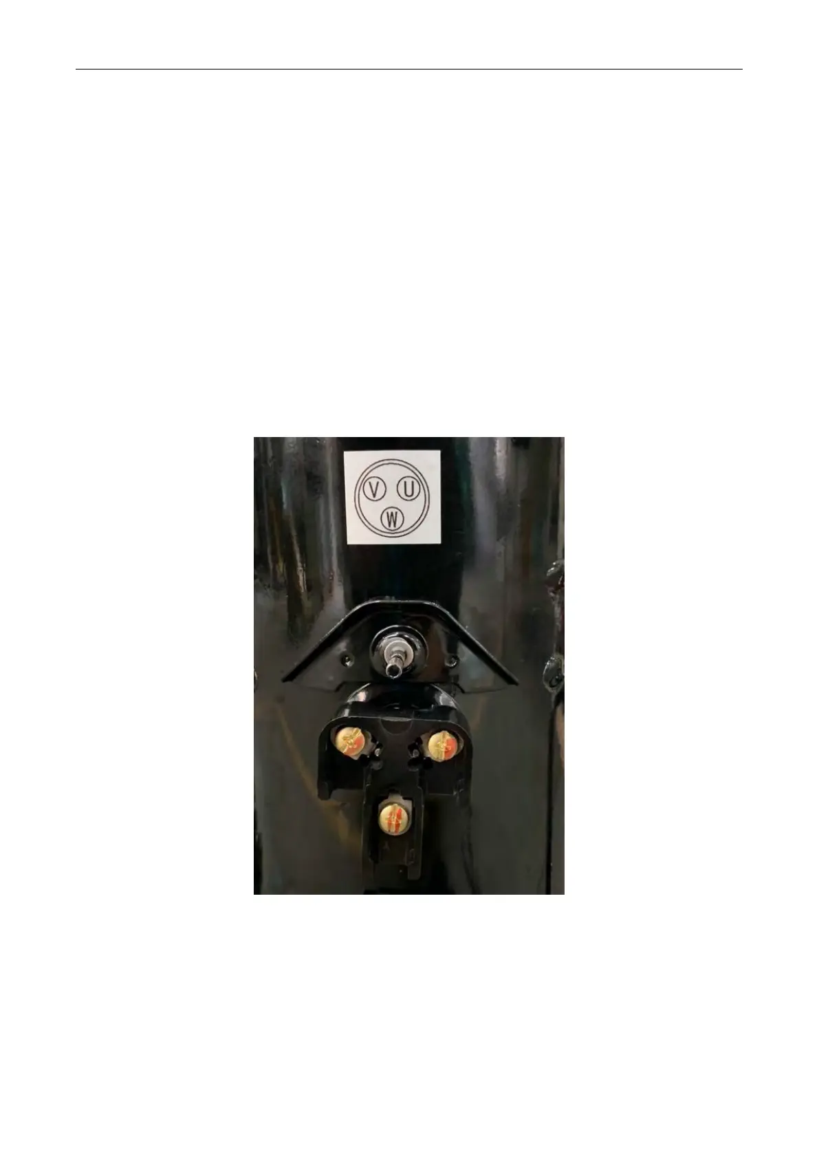
Step 1:
Disconnect the unit from power. Remove the terminal box cover and check whether the compressor
is wired correctly.
Step 2:
Measure the resistance between any two of the wiring terminals of the compressor (U, V and W).
The resistance between two wiring terminals of AA55PHDG-D1Y2 is 0.197±7% Ω. The resistance
between two wiring terminals of DA80PHDG-D1Y2 is 0.086±7% Ω.
Measure the grounding resistance of each wiring terminal, which should be greater than 10 MΩ;
otherwise, the compressor has an internal fault.
Step 3:
When the unit cannot be started properly, the solenoid valves of the system, including the electronic
expansion valve and oil-return valve, need to be checked using the same method described above.
Step 4:
Check the IPM module using the same method described above.
 Loading...