Gree GMV6 DC Inverter VRF Units Service Manual
CA On 02 On OC On
Modules not shielded display as follows:
Press the SW4 back button. Modules not shielded display normal working status, and the shielded
module displays as follows:
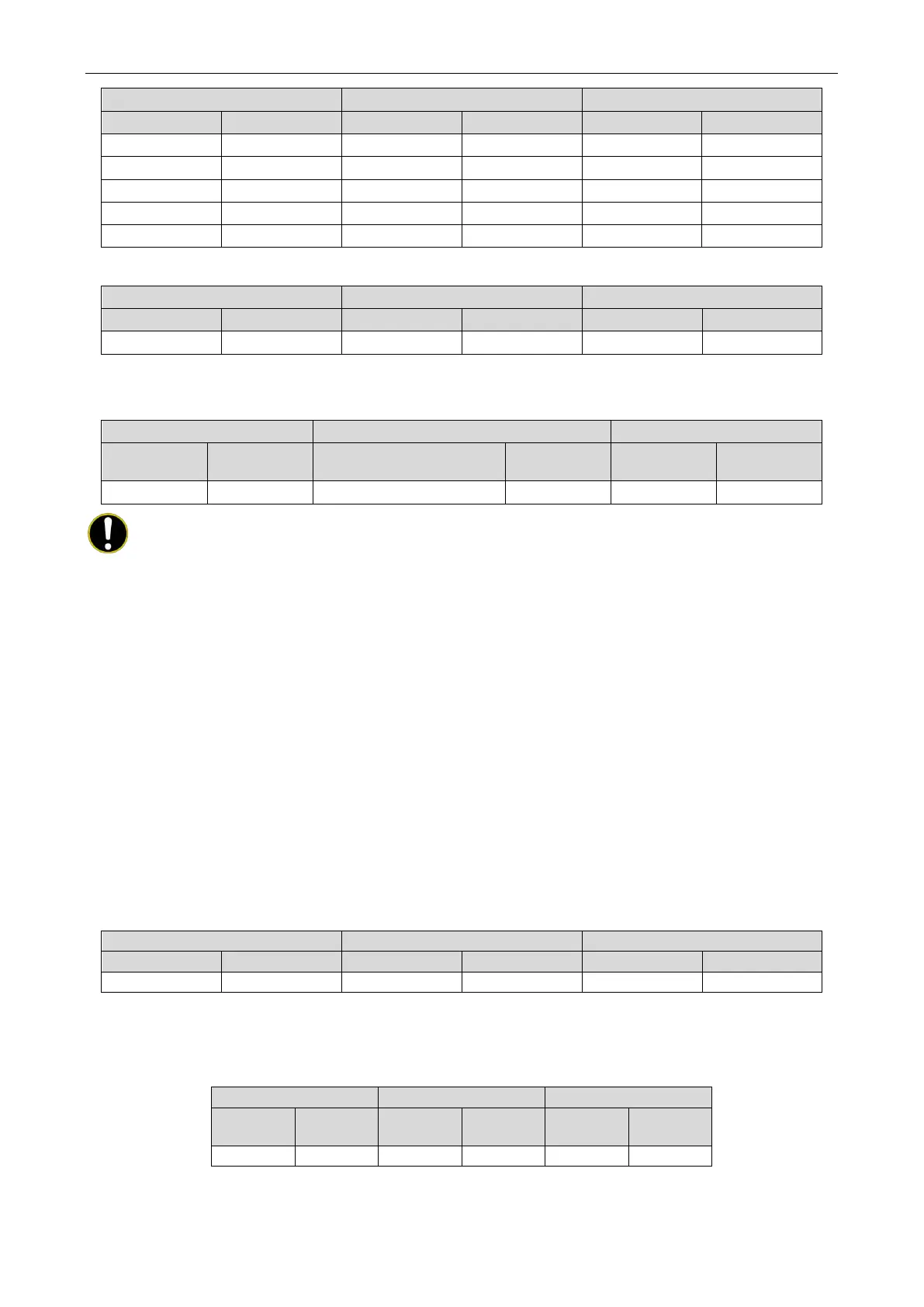
Module
Display status
Module failure/indoor unit
Display status Module status Display status
NOTES!
① This function is valid only in systems with two or more modules connected in parallel;
② A system can set only one module to emergency mode;
③ The default status is 00.
④ The system cannot run continuously for more than 48 hours in module emergency
operation status. If it exceeds 48 hours, the entire system is stopped, and the indoor unit
displays the "Ad" limit operation code.
4.2.3.14 4J Emergency setting of components
Emergency setting of components
The emergency setting of components is used for the after-sales emergency setting when some
components of the unit work abnormal, to remove the fault protection of abnormal components in a short
time and ensure the emergency operation of the unit.
Setting operation:
Enter the function setting on the main control machine's main board, which is shown as follows:
Press SW1 to select the key above and SW2 to select the key below to select the corresponding
value of 00 or 01, in which 00 represents "emergency state of non-components" and 01 represents
"emergency state of components". The factory default is 00.
Function
Display
Current
Display
Current
Display
After selecting the corresponding value, press SW3 to confirm the key, and the main module will be
 Loading...