Do you have a question about the ASC Signal NGC-ODU-208-3 and is the answer not in the manual?
| Brand | ASC Signal |
|---|---|
| Model | NGC-ODU-208-3 |
| Category | Antenna |
| Language | English |
Provides preventive maintenance, troubleshooting, and corrective maintenance information for the NGC Antenna Controller Outdoor Unit (ODU).
Specifies that installation, maintenance, and removal require qualified and experienced personnel.
Covers proprietary information and notes on product design changes.
Explains safety symbols and the caution required when operating components.
Defines safety terms like DANGER, WARNING, CAUTION, and PRUDENCE used in the manual.
Outlines essential safety precautions such as keeping away from live circuits and not servicing alone.
Lists critical actions to avoid, such as touching live circuits or servicing alone.
Instructions on verifying received shipment against packing slip before installation.
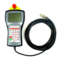
Details how to connect the handheld controller to the NGC-ODU, including ESTOP procedures.
Explains the function of each button on the handheld controller's keypad.
Illustrates the general menu tree and navigation flow for the handheld controller.
Describes the HOME SCREEN and its button ribbon options for general users.
Details the JOG SCREEN for moving the antenna and viewing feedback.
Explains the GoTo SCREEN for precise antenna movement and target setting.
Overview of parameter screens displaying system status and configuration.
Displays a list of all active faults for the NGC-ODU.
Allows viewing of historical pop-up messages logged by the handheld controller.
Guides users through the setup interview process for configuring parameters.
Provides access to advanced diagnostic functions and commands.
Allows users to enter and exit installer mode using passwords.
Displays general system information such as software version and time/date.
Highlights installer-specific screens like Edit Fractions and Search.
Feature to quickly find specific parameter screens via a shortcut list.
Diagram of the NGC Outdoor Unit with numbered components.
Identifies and describes the purpose of ODU connectors and cable glands.
Details the MC-7 PWA as the master controller for the NGC-ODU.
Explains the function of Axis Control Units in providing loop closure for motors.
Describes the ASU's role in reading angular feedback and limit conditions.
Details the Elevation and Azimuth Variable Frequency Drives (VFDs).
Information on the A10 Power Supply Board providing power to the ODU.
Descriptions of various components like thermostats, heaters, and circuit breakers.
Details the purpose and designations of terminal blocks TB1 through TB4.
Describes the EWI-1 board for terminating field-installed wiring.
Describes the EWI-2 board for high-accuracy SSI-based optical encoders.
Troubleshooting flowchart for issues when the antenna won't jog or move.
Troubleshooting steps for incorrect movement direction or display values.
Scenarios and solutions for movement and wiring problems in Az/El axes.
Flowcharts for troubleshooting when the polarization axis does not move correctly.
Addresses scenarios like polarization axis not displayed or moving incorrectly.
Troubleshooting for handheld terminal not working or NGC-IDU communication faults.
Procedures for general cleaning of the NGC ODU components.
Methods for cleaning dust and foreign particles from electrical components.
Procedures for cleaning dust, dirt, and contaminants from mechanical parts.
Guidelines for performing monthly visual inspections and annual checks.
Instructions for cleaning and painting aluminum components.
Actions to take in case of moisture or water ingress into the ODU.
List of VFD spare kits available for maintenance.
Details the NGC-SPR-ODU-PS module including its power supplies.
Lists available spare boards like MC-7, ACU-2, ASU-2, EWI-1, and SPU-1.
Information on the spare Pol Interface Assembly kit.
Details spare kits for low temperature protection (heater, thermostat, relay).
Lists part numbers for various circuit breakers used in the ODU.
Kit contents for the spare Emergency Stop components.
Information on the spare programmed handheld terminal and tethered plug.
List of error codes displayed by PWAs indicating status or faults.
Table showing rotary switch settings for MC, ACU, and ASU boards.
Glossary of faults reported by the NGC-ODU system.
Block diagram illustrating the NGC-ODU system components and connections.
Block diagram of the NGC antenna control system, showing IDU and ODU interaction.
Defines the NGC-ODU's responsibilities for pointing and interfacing.
Describes the fundamental control electronics components of the NGC-ODU.
Explains the NGC Bus structure, protocol, and cable types.
Details system configurations like 'Fixed', 'Mobile', and 'SRT Only'.
Explains how the NGC-ODU implements movement commands from IDU or handheld.
Describes how angular feedback is obtained and processed from resolvers/encoders.
Explains the function of limit switches and how hard/soft limits work.
Details how the emergency stop signal is processed by the ACU-2 PWA.
Explains how jog commands are implemented via direct drive signals.
Describes PID feedback control systems for Azimuth and Elevation axes.
Explains the ON/OFF control system with deadband for the polarization axis.
How the ODU transforms platform attitudes for the IDU's true pointing angles.
Details the SRT Carriage Assembly for tracking small movements.
Software function to allocate movement between main axes and SRT.
Information on accessories like the AS-1 Attitude Sensor.
Alphabetical list of handheld terminal parameters with descriptions and ranges.
Limit conditions for axes with clockwise and counterclockwise directions.
Limit conditions for axes with up and down directions.
Extra inputs for azimuth axis in customized installations.
Extra inputs for elevation axis in customized installations.
Summary field for cabinet power status.
Lists PWAs that may be installed on the NGC Bus.
Legal values for the compass calibration field.
List of compass faults that may be reported.
Compass modes selectable in TriFold configuration.
List of GPS faults reported by an AS-1 module.
GPS quality values returned by the AS-1.
Fields to disable unused limit inputs.
Values for local/remote control settings.
Axis movement faults that can be reported.
Commanded functions that can be entered for SRT and Pol.
Summary of the SRT's overall status.
Summary of the SRT temperature.
Indicates if the Z axis of an XYZ SRT has a limit fault.
Track modes reported by the NGC-ODU from NGC-IDU data.
Track states reported by the NGC-ODU from NGC-IDU data.
Statuses of the Modbus for each control unit.
Lists encoder and resolver types typically used with EWI-2.
Table of diagnostic commands, their purpose, and consequences.
