ASCO Valves
®
E286170 - 07/2018 All Rights Reserved. I&M V_7221_R7
©
ASCO, L.P.
160 Park Avenue, Florham Park, New Jersey 07932 www.asco.com Page 1 of 4
I&M V_7221_R7
Installation & Maintenance Instructions
OPEN-FRAME, GENERAL PURPOSE, WATERTIGHT/EXPLOSIONPROOF SOLENOIDS
SERIES
8017G
8014G
NOTICE: See separate valve installation and maintenance
instructions for information on: Operation, Positioning,Mounting,
Cleaning, Preventive Maintenance, Causes of Improper Operation,
Disassembly and Reassembly of a basic valve.
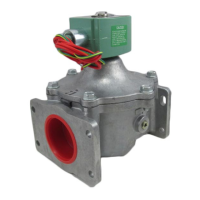
DESCRIPTION
Series 8017G and 8014G are epoxy encapsulated solenoids. The green
solenoid with lead wires and 1/2” conduit connection is designed to
meet Enclosure Types 1 - General Purpose, Type 2-Dripproof, Types 3
and 3S-Raintight, and Types 4 and 4X-Watertight. The black solenoid
on catalog numbers prexed “EF” is designed to meet Enclosure
Types 3 and 3S-Raintight, Types 4 and 4X-Watertight, Types 6
and 6P-Submersible, Type 7 (A, B, C & D) Explosionproof Class I,
Division1 Groups A, B, C, & D and Type 9 (E & F) -Dust-Ignitionproof
Class II, Division1 Groups E & F. See Temperature Limitations section
for solenoid identication and nameplate/retainer for service. When
Series 8017G is installed just as a solenoid and not attached to an ASCO
valve, the core has a 0.250-28UNF-2B tapped hole, 0.38 minimum full
thread.
Catalog numbers 8017G1 and 8017G2 are pull type direct-acting
solenoids, while Catalog Nos. 8014G1 and 8014G2 are push type
reverse-acting solenoids.
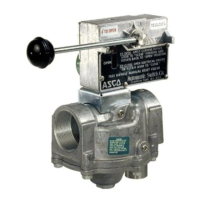
General purpose solenoids (green) are available in open-frame
construction. This construction may be supplied with 1/4” spade, screw
or DIN terminals (Refer to Figure 2).
Optional Features for Type 1 - General Purpose Construction
Only
• Junction Box: This junction box construction meets Enclosure
Types 2, 3, 3S, 4, and 4X. Only solenoids with 1/4˝ spade or screw
terminals may have a junction box. The junction box provides a
1/2˝ conduit connection, grounding and spade or screw terminal
connections within the junction box (See Figure 3).
• DIN Plug Connector Kit No. K236034: Use this kit only for
solenoids with DIN terminals. The DIN plug connector kit provides
a two pole with grounding contact DIN Type 43650 construction
(See Figure 4).
NOTE: For China RoHS Hazardous Substances table,
please go to the link below or scan QR code:
www.asco.com/ChinaRoHSDisclosure
OPERATION
Series 8017G - When the solenoid is energized, the core is drawn into
the solenoid base sub-assembly. IMPORTANT: When the solenoid
is de-energized, the initial return force for the core, whether
developed by spring, pressure, or weight, must exert a minimum
force to overcome residual magnetism created by the solenoid.
Minimum return force 1 pound, 12 ounces.
Series 8014G - When the solenoid is energized, the disc holder
assembly seats against the orice. IMPORTANT: Initial return force
for the disc or disc holder assembly, whether developed by spring,
pressure, or weight, must exert a minimum force to overcome
residual magnetism created by the solenoid. Minimum return force
is 1 pound, 12 ounces. When the solenoid is de-energized, the disc
holder assembly returns.
INSTALLATION
Check nameplate for correct catalog number, service, and wattage.
Check front of solenoid for voltage and frequency.
WARNING: Electrical hazard from the
accessibility of live parts. To prevent the possibility
of death, serious injury or property damage, install
the open - frame solenoid in an enclosure.
AVERTISSEMENT: Risque d’accès aux parties
électriques actives. An d’éviter tout risque de
mort, blessure ou dommage, installer la bobine
dans un boitier.
FOR BLACK ENCLOSURE TYPES 7 AND 9 ONLY
CAUTION: To prevent re or explosion, do not install
solenoid and/or valve where ignition temperature of
hazardous atmosphere is less than 180°C.
ATTENTION : An d’éviter le risque de feu ou d’explosion,
ne pas installer la bobine ou l’électrovanne ou la température
d’inammation en atmosphère explosible est inferieure à
180°C.
NOTE: These solenoids have an internal non-resetable thermal fuse to
limit solenoid temperature in the event that extraordinary conditions
occur which could cause excessive temperatures. These conditions
include high input voltage, a jammed core, excessive ambient
temperature or a shorted solenoid, etc. This unique feature is standard
on solenoids with black explosionproof/dust-ignitionproof enclosures
(Types 7 & 9).
CAUTION: To protect the solenoid valve or operator,
install a strainer or lter, suitable for the service involved in
the inlet side as close to the valve or operator as possible.
Clean periodically depending on service conditions. See
ASCO Series 8600 and 8601 for strainers.
ATTENTION : An de protéger l’électrovanne ou
l’actionneur, installer une crépine ou un ltre adapté le
plus proche possible en amont de l’électrovanne ou de
l’actionneur. Nettoyer périodiquement le ltre en fonction
des conditions d’utilisation. Se référer aux séries 8600 et
8601 pour les crépines.
Temperature Limitations
For maximum valve ambient temperatures, refer to chart. The
temperature limitations listed, only indicate maximum application
temperatures for eld wiring rated at 90°C. Check catalog number
prex and watt rating on nameplate to determine maximum ambient
temperature. See valve installation and maintenance instructions for
maximum uid temperature.
NOTE: For steam service, refer to Wiring section, Junction Box for
temperature rating of supply wires.
®
Temperature Limitations For Series 8017G or 8014G Solenoids for
use on Valves Rated at 16.1 or 20.1 Watts
Watt
Rating
Catalog
Number Coil Prex
Class of
Insulation
Maximum §
Ambient Temp.
16.1
None, KF, KP, SD, SF
& SP
F 125°F (52°C)
20.1
FB, KF, KP,
SD, SF & SP
F 104°F (40°C)
16.1
None, KB, KH,
SS, ST & SU
H
140°F (60°C)
125°F (52°C) For
Steam Service
20.1
HB, KH,
SS, ST, SU & SV
H
140°F (60°C)
Not for Steam Service
§ Minimum ambient temperature -40°F (-40°C).