50 Hanover Road, Florham Park, New Jersey 07932 www.ascovalve.com
Form No.V8714 - Sec. 1
Page 4 of 6 (Section 1 of 2)
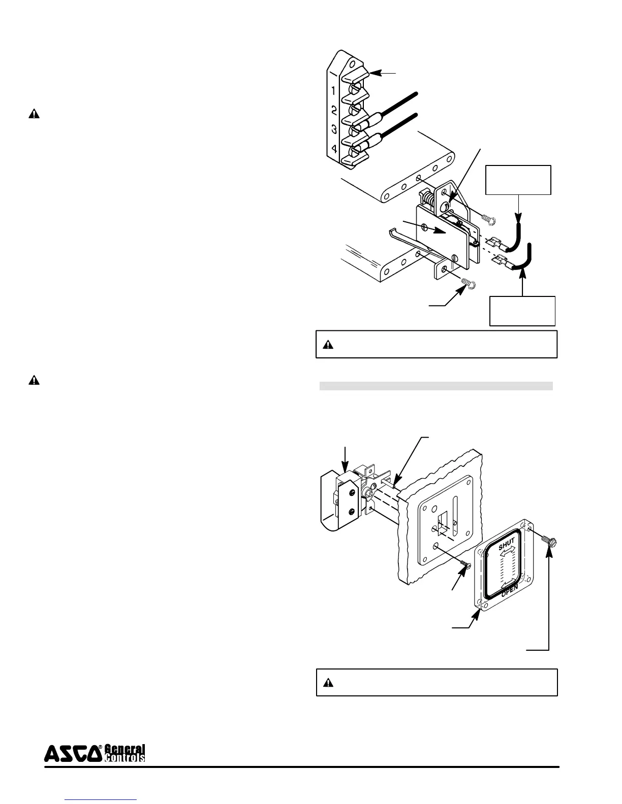
Travel Limit Switch Replacement (Refer to Figure 5)
1. Remove the six cover screws and nameplate/electrical
cover with gasket.
2. Disconnect wiring from travel limit switch.
CAUTION: Label wires before disconnecting.
3. Remove two mounting screws and the travel limit switch.
4. Reinstall new travel limit switch in actuator. Torque
mounting screws (2) evenly to 20 to 25 in-lbs [2,3 to 2, 8
Nm].
5. The required stroke is 1 1/8 1/16. Turn adjustment
screw located above limit switch until the desired stroke
is achieved. Turn the adjustment screw clockwise to
decrease stroke and counterclockwise to increase stroke.
6. Operate actuator (complete system) through five cycles to
verify proper operation.
7. Reinstall nameplate/electrical cover with gasket and
screws (6) on actuator housing. Hand thread screws as far
as possible, then torque screws evenly in a crisscross
manner to 30 to 35 in-lbs [3 ,4 to 4, 0 Nm].
Auxiliary Switch Replacement (Refer to Figure 6)
1. Remove six cover screws and nameplate/electrical cover
with gasket.
2. Disconnect auxiliary switch wiring.
CAUTION: Label wires before disconnecting.
3. On auxiliary switch side of actuator, remove window
screws (4) and window with gasket.
4. Remove auxiliary switch mounting screws (2) from side of
actuator.
5. Disengage auxiliary switch from indicator bar and remove
switch from actuator.
6. Install new auxiliary switch and reassemble in reverse
order of disassembly.
7. Torque auxiliary switch mounting screws (2) evenly to 14 to
16 in-lbs [1, 6 to 1,8 Nm].
8. Torque terminal screws 8 to 12 in-lbs [0, 9 -1, 3 Nm].
9. Reinstall the window with gasket and torque screws
evenly to 14 to 16 in-lbs [1,6 to 1,8 Nm].
10. Reinstall nameplate/electrical cover with gasket and
screws (6) on actuator housing. Hand thread screws as far
as possible, then torque screws evenly in a crisscross
manner to 30 to 35 in-lbs [3 ,4 to 4, 0 Nm].
11. Operate actuator (complete system) through five cycles to
verify proper operation.
Figure 5. Travel Limit Switch Replacement.
Main terminal
Travel limit switch
Adjustment screw
Mounting screw (2)
Partial Cutaway View
Connect to
Terminal 3
Connect to
Terminal 4
CAUTION: Label wires before disconnecting.
Figure 6. Auxiliary Switch Replacement.
Auxiliary switch
Position indicator bar
Switch mounting screw (2)
Partial Cutaway View (Right Side)
Window with gasket
Window screw (4)
CAUTION: Label wires before disconnecting.
Continued on Form No. V8714-Section 2.
 Loading...