Page 9 of 16
5 Marking of the device
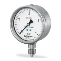
The nameplate with serial number and type designation is located on the housing. The materials used for the wetted
parts as well as other device-specific versions are represented by a type coding on the nameplate and can be broken
down at any time with the aid of the data sheet. The marking for the hazardous areas, in the form of the description of
the type of protection, the permissible ambient temperature and the deposit number, are located in the lower area of the
nameplate. If the differential pressure gauge is specified with an integrated inductive proximity switch the electrical
parameters are mentioned on the name plate.
6 Construction and function
6.1 Overview
1. Tube
2. Spring support and process connection
3. Measuring system
4. Pointer
5. Dial
6. Window
7. Bayonet ring
8. Seal
9. Venting valve
10. Case
11. Blow-out spout/compensation diaphragm
6.2 Description of function
An elastic measuring element in the form of a Bourdon tube (circular or helical, depending on the measuring range) is
welded to a socket. It is pressurized on one side from the inside. A pressure transmission medium can be gaseous or
liquid, depending on the material and design used.
Pressure loading causes elastic deflection from the normal position. This deflection is proportional to the applied
pressure. At the end of the Bourdon tube, a tension rod picks up the deflection and transmits it to a movement. The
measured value is displayed on a 270° scale.
The requirements for indicating pressure gauges with Bourdon tubes are in accordance with EN 837-1.
The device is equipped with inductive contact switches with non-contacting electrical proximity sensors (proximity
switches) in accordance with DIN EN 60947-5-6 (NAMUR).
The output signal is determined by the presence and absence of a control vane moved by the actual value pointer in the
area of the electromagnetic field of the proximity switch. An adjustment lock with a separate or permanently mounted
key is used to set the setpoint pointers of the built-in limit switch contact assemblies from the outside to the setting at
which the switching operation is to take place.

 Loading...