This document describes the Aspira S-0241.02 Remote Control, a control display for UVR-HE systems.
Function Description
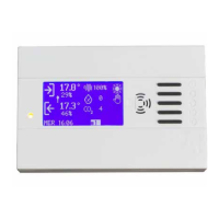
The S-0241.02 is a remote control unit designed to manage and monitor various parameters of a ventilation and exhaust system. It allows users to control fan speeds, monitor CO2 and humidity levels, set temperatures, and manage sterilization functions. The device features a display that shows real-time data and provides access to a menu for configuration and operation.
The control unit can be used to set the supply and exhaust fan speeds, with the bypass damper opening and closing. It can also manage the speed of one or two fans, ensuring that the speed is always a fraction of the reference. If there are probes for CO2, moisture, or temperature, the measured value is shown on the panel of the remote control.
The "AUTOMATIC" mode allows both the fans and the bypass to be managed by the control without any possibility of intervention by the user. The fan speed changes automatically to maintain the carbon dioxide level measured in the room, below the reference value set by the user. The bypass damper opens and closes automatically according to the reference temperature set by the user.
The "MENU" provides access to various settings, including language, display back-lighting, date/time, season, and modes of operation (AUTO, MAN, PROGRAMS). It also allows for ON/OFF system control, bypass control, and adjustment of command percentage supply and exhaust fan.
The device includes visual and differentiated alarm indicators. A red belt and the word "REPLACE AIR FILTER" indicate a clogged filter, while a green belt and "SANITIZATION ALARM" appear when the main voltage disappears (230V a.c.). The bell with the words "SANITIZATION ALARM" appears and remains for 10 minutes (time adaptable to customer needs) after the restoration of the entrance. The sanitization alarm also activates immediately after Ozone generator operation.
The sterilizer protocol management with related calendar allows for activation/deactivation in the menu, administrator card. Through the sterilizer calendar, you can choose 2 trigger/deactivation time for each day of the week, with a maximum duration of 2 hours.
The implement the firefighting function allows for an active entire system stop and a flashing error message on the home screen. The firefighting function can be disabled in the menu, administrator card.
Humidity sensor can be activated/deactivated in the menu, administrator card.
The control card can manage up to 32 addresses, meaning 32 different units with a single electronic one. It is possible to configure the Baud Rate used (9600 – 19200 – 115200), adding a new heading in the display menu.
Important Technical Specifications
The S-0241.02 remote control communicates via RS485 Modbus. It connects to the product S-0277-00 using specific connectors. The display is powered by 12V and GND connections.
The device supports up to 32 slave units. The Baud Rate can be configured to 115200, 9600, or 19200, depending on the DIP switch settings (DIP 6 and DIP 7 on the SW1 card). The maximum address for these cards is 16.
The Modbus protocol defines various registers for controlling and monitoring the system:
- SLAVE_VERSION (0x00): Read-only, provides firmware version information (0=S0242, 1=S0283).
- COMMAND (0x01): Write-only, allows for flash saving of registers, bypass commands (0x03), and firmware updates (0x04).
- DATETIME_DD_MM (0x02): Read/Write, for day and month settings.
- DATETIME_YY_H (0x03): Read/Write, for year and hours settings.
- DATETIME_M_S (0x04): Read/Write, for minutes and seconds settings.
- IO (0x05): Read-only, provides status of various inputs and outputs (DIN_HV1, DIN_HV2, DIN_TERMOST, DIN_FILTER, RELE_FAN1, RELE_FAN2, RELE_BATT, RELE_FCOM, RELE_AUX1, RELE_BYPASS).
- CO2 (0x06): Read-only, displays CO2 sensor value in ppm.
- AUX1 (0x07), AUX2 (0x08): Read-only, input value for AUX1 and AUX2 in count.
- TEMP_EXT (0x09): Read-only, outside temperature value (in **10).
- TEMP_INT (0x0A): Read-only, inside temperature value (in **10).
- H2O_VALUE (0x0B): Read-only, command applied on the H2O output, in %.
- STATUS (0x12): Read/Write, machine status (Modes, Bypass status, System status, Fan speed, Filter status, Firefighting status, Tacho Fan status, Sanitization alarm status).
- SEASON (0x0D): Read/Write, set season (0=winter, 1=summer).
- THERMOSTAT (0x0E): Read/Write, thermostat (0=not in the system, 1=in the system).
- AIR_QUALITY (0x0F): Read/Write, air control (0=not in the system, 1=in the system).
- CO2_SETPOINT (0x10): Read/Write, CO2 setpoint in ppm (is valid if the air control is enabled).
- ROOM_SETPOINT (0x11): Read/Write, temperature setpoint.
- FAN2_FAN1 (0x12): Read/Write, supply command Bit 7..0: % return command.
- MAX_FAN_MIN_FAN (0x13): Read/Write, max command % applicable to the fan outlets Bit 7..0: Min. command % applicable to the fan outlets.
- REAL_FAN2_FAN1 (0x14): Read-only, supply command applied in this moment Bit7..0: % return command applied in this moment.
- PROG_N_START (0x15 to 0x2F): Read/Write, trigger time for programs (1 to 14).
- PROG_N_STOP (0x16 to 0x30): Read/Write, deactivation time for programs (1 to 14).
- STERILIZER_PROG_N_START (0x31 to 0x4B): Read/Write, activation output sterilizer (1 to 14).
- STERILIZER_PROG_N_STOP (0x32 to 0x4C): Read/Write, deactivation output sterilizer (1 to 14).
- STERILIZER (0x4D): Read/Write, sterilizer (0=not in the system, 1=in the system).
- ANTIFIRE (0x4E): Read/Write, firefighting (0=not in the system, 1=in the system).
- HUMIDITY_SENSOR (0x4F): Read/Write, humidity sensor (0=not in the system, 1=in the system).
- HUMIDITY_VALUE (0x50): Read-only, humidity value read by the sensor, in %.
- TACHO_FAN_1 (0x51): Read-only, tachymetric value fan 1 read in this moment, in Hz.
- TACHO_FAN_2 (0x52): Read-only, tachymetric value fan 2 read in this moment, in Hz.
Usage Features
The S-0241.02 is designed for easy assembly and use. It can be mounted directly on an in-wall box, type 503, using provided screws. The connections for power (12V, GND) and RS485 (A1, B1, A2, B2) are clearly labeled.
The display features several buttons for navigation and control:
- ON-OFF button: Toggles the device on/off.
- Decrease button: Decreases values or moves through menu options.
- Increase button: Increases values or moves through menu options.
- MENU button: Accesses the main menu.
- BY-PASS actuation button: Activates bypass (at all pressure switches).
- Sounder: Activates an audible alert.
- Two-tone LED (red/green) ON-OFF - filter replacement: Indicates filter status.
- Exclamation point - possible engine malfunction: Indicates a potential issue with the motor.
The LED display provides visual feedback:
- If the fans (of every control cards) are off or activated with a command that is lower than 30%, the LED stays OFF.
- Otherwise, the LED lights up green or, if one of the filter is dirty and its entrance is active, it lights up red.
- The filter entrances are considered only on cards with command FAN that are higher than 30% (>30%).
The device offers various operational modes:
- Manual functioning: Allows direct control of fan speeds and other parameters.
- Automatic functioning: System automatically adjusts parameters based on sensor readings.
- Functioning with schedule: Allows programming daily or weekly schedules for operation.
The menu structure allows for extensive customization:
- Up to 32 recovery units can be set.
- Three different languages can be set: Italian, Spanish, English.
- Illumination and contrast of the display can be set.
- Buzzer can be enabled or disabled.
- Baud Rate can be configured (115200, 9600, 19200).
- Speed of the supply fan (OUTSIDE AIR) can be modified.
- Speed of the exhaust fan (INSIDE AIR) can be modified.
- Mode of operation can be modified: SUMMER / WINTER.
- Reference temperature, heating and cooling coil can be modified (temp °C min: 20 Max + 80).
- Reference threshold PPM (Co2) standart threshold 600/800. It works only in automatic mode.
- Two types of probes can be selected: standart 2000 ppm, probe 5000 ppm or you can exclude all the probes in mode NO.
- Thermostat option can be activated or deactivated. If it is activated without probe, on the display the value 0 will appear. Use the 0_10 Volt sensor.
- Programming the machine set hour and date.
- Selecting PROGRAMS mode.
- Setting two daily programs per week: Monday starting at 08:00 and shutdown at 12:00, starting at 13:00 and shutdown at 17:00 all week.
- Sterilizer (UVC/OZONE lamps) can be set ON/OFF option (OFF).
- Sanitization method (OPTIONAL) can be used with UVC lamps. OZONE (DURING SANITIZATION, STAFF MUST NOT BE IN THE ROOM).
- Sanitization method (OPTIONAL) can be used with two daily programs. For example, Monday starting at 20.00 and shutdown at 22.00, starting at 00.00 and shutdown at 02.00; MAX 2 hours per week.
- Moisture sensor can be used. If it activated without probe, on the display the value 0 will appear. Use the 0_10 Volt sensor.
- Sprinkler system of the room can be used. Use Pin N.8 of the contact card (N0) generator open. In case of fire, the recuperator stops. The signal "FIRE ALARM" will appear on the display.
- Minimum of the two fans can be regulated. We do not recommend modifying it under 20%.
- Maximum of the two fans can be regulated. When modified the fan speed for > 80%, it is no longer possible to exceed the 80% on both fans (SUPPLY/EXHAUST).
- TACHO FANS: FAN 1 indicates the frequency in Hz of the supply fan. FAN 2 indicates the frequency in Hz of exhaust fan.
Maintenance Features
The manual highlights the importance of proper installation and configuration for optimal performance.
- Installation activities must be entrusted to qualify staff.
- L'alimentazione del Display è fornita dall'UNITA' DI CONTROLLO MOTORI. (The display is powered by the MOTOR CONTROL UNIT).
- Communication speed: To set the Baud Rate of a SLAVE card, use the dip switch 6 and 7 present on the card [SW1]. Changes must be made when the machine is not connected to the mains. Set the same baud rate configured on the display card (MASTER) through the configuration menu.
- Error Handling: If the phrase "COMMUNICATION ERROR" appears, you have to configure the card of the recovery unit by using the SWITCH 6-7 on the card with the same speed of the Display. Changes must be made when the machine is turned OFF.
- Disposal: The product conforms to EU directive 2002/96/EC. The symbol of the barred waste bin indicates that, at the end of its useful life, the product has to be collected separately from domestic waste. The user will have to take the product to a collection centre for waste electrical and electronic equipment, or return it to a retailer on purchase of a replacement. Failure to do so may incur the penalties established by laws governing waste disposal. Proper differential collection and the subsequent recycling, processing and environmentally compatible disposal of waste equipments avoids unnecessary damage to the environment and possible related health risk and promotes also recycling of the materials used in the appliance.