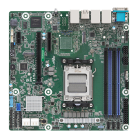
B650D4U-1L
B665D4U-1L
6 7
English
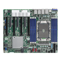
No. Description
1 2 x 288-pin DDR5 DIMM Slots (DDR5_A2, DDR5_B2)*
2 2 x 288-pin DDR5 DIMM Slots (DDR5_A1, DDR5_B1)*
3 ATX 12V Power Connector (ATX12V1)
4 ATX 12V Power Connector (ATX12V2)
5 Clear CMOS Pad (CLRCMOS1)
6 ATX Power Connector (ATXPWR1)
7 System Fan Connector (FAN1)
8 System Fan Connector (FAN7)
9 System Fan Connector (FAN6)
10 AMD Socket AM5 (LGA 1718)
11 PWM Conguration Header (PWM_CFG1)
12 SPI TPM Header (TPM_BIOS_PH1)
13 SATA3 Connectors (SATA_1)(Upper), (SATA_0)(Lower)
14 SATA3 Connectors (SATA_3)(Upper), (SATA_2)(Lower)
15 System Fan Connector (FAN4)
16 System Fan Connector (FAN3)
17 Auxiliary Panel Header (AUX_PANEL1)
18 System Panel Header (PANEL1)
19 System Fan Connector (FAN5)
20 USB 3.2 Gen1 Header (USB3_7_8)
21 USB 2.0 Header (USB_1_2)
22 OCuLink x4 Connector (OCU1)
23 System Fan Connector (FAN2)
24 Speaker Header (SPEAKER1)
25 PCI Express 4.0 x1 Card Slot (PCIE4)
26 PCI Express 5.0 x16 Card Slot (PCIE6)
27 PCI Express 5.0 x4 Card Slot (PCIE7)
28 M.2 Socket (M2_2) (Type 2242/2280)
* For DIMM installation and conguration instructions, please see p.18 (Installation of Memory Modules
(DIMM)) for more details.
 Loading...