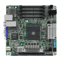
X570D4U-2L2T / X570D4U
32 33
English
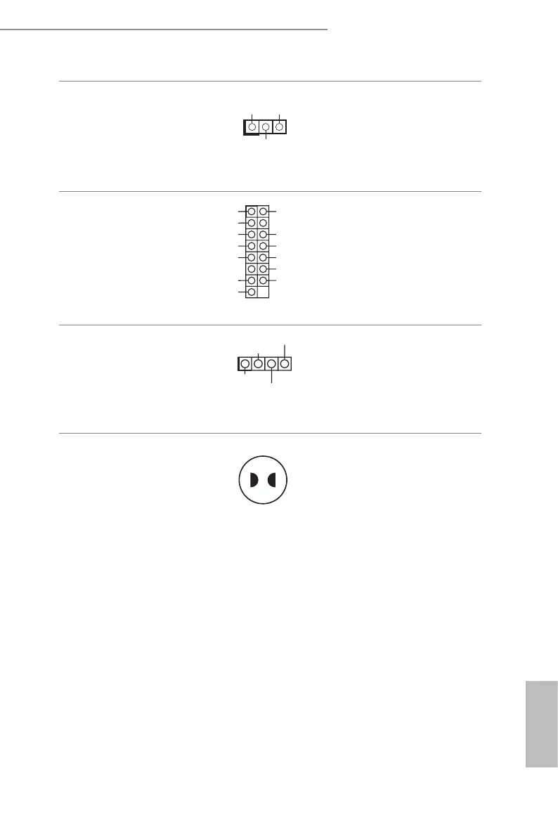
ermal Sensor Header
(3-pin TR1)
(see p.7, No. 22)
1
TR1 TR1
GND
Please connect the thermal
sensor cable to either pin 1-2
or pin 2-3 and the other end to
the device which you wish to
monitor its temperature.
Front VGA Header
(15-pin FRNT_VGA1)
(see p.7, No. 36)
G ND
Green
DDC_DATA
V_SYNC
Red
D DC_CLK
+5V
H_SYNC
G ND
G ND
Blue
G ND
G ND
Please connect either end
of VGA_2X8 cable to VGA
header.
Front LAN LED
Connector
(LED_LAN_3_4)
(see p.7, No. 35)
(X570D4U-2L2T only)
1
LAN3_LINK
LED_PWR
LED_PWR
is 4-pin connector is used
for the front LAN status
indicator.
Clear CMOS Pad
(CLRCMOS1)
(see p.7, No. 25)
is allows you to clear the
data in CMOS. To clear CMOS,
take out the CMOS battery and
short the Clear CMOS Pad.
 Loading...