Do you have a question about the ASROCK B365M-HDV and is the answer not in the manual?
Lists the items included in the motherboard package.
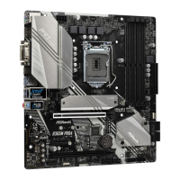
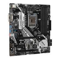
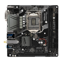
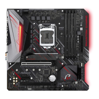
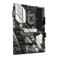
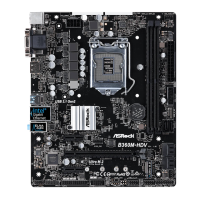
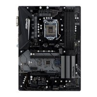
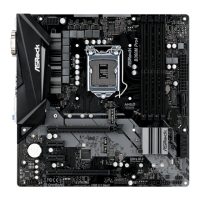
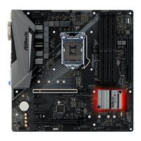
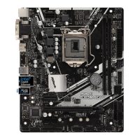
Specifies the motherboard form factor and design features.
Details CPU compatibility and technologies supported.
Identifies the motherboard chipset.
Describes memory technology, slots, and capacity.
Lists PCI Express slot types and configurations.
Details integrated graphics capabilities and supported features.
Details audio features, codec, and protection.
Describes LAN controller and features.
Lists the connectors available on the rear I/O panel.
Details SATA and M.2 storage connectors and capabilities.
Lists various onboard headers and connectors.
Outlines BIOS functionalities and support.
Describes hardware monitoring features like temperature and fan speed.
Specifies the supported operating system.
Lists regulatory and safety certifications.
Lists essential precautions before installing motherboard components.
Provides step-by-step instructions for CPU installation.
Guides on how to install the CPU fan and heatsink assembly.
Details the procedure for installing DDR4 memory modules.
Explains the types and usage of PCI Express slots.
Explains jumper configurations and their functions.
Explains how to clear CMOS settings using a jumper.
Details various onboard headers and their connection points.
Details the system panel header for power/reset buttons and LEDs.
Explains the header for chassis intrusion detection and speaker.
Lists and describes the six SATA3 connectors.
Details the two USB 2.0 headers and their port capacity.
Explains the USB 3.1 Gen1 header and its port capacity.
Details the front panel audio header and connection instructions.
Explains the chassis and water pump fan connectors.
Details the 4-pin CPU fan connector and its compatibility.
Explains the 24-pin ATX power connector and usage with 20-pin supplies.
Details the 8-pin ATX 12V power connector and usage with 4-pin supplies.
Explains the COM1 header for serial port modules.
Details the TPM header for secure key storage and platform integrity.
Explains the LPT1 header for printer connections.
Guides through the process of installing an M.2 SSD.
Provides steps for mounting and securing the M.2 SSD.
| Audio chip | Realtek ALC887 |
|---|---|
| Certification | FCC, CE, ErP/EuP |
| Component for | PC |
| Motherboard chipset | Intel B365 |
| PC health monitoring | FAN, Temperature, Voltage |
| Audio output channels | 7.1 channels |
| Motherboard form factor | micro ATX |
| Motherboard chipset family | Intel |
| Windows operating systems supported | Windows 10 Education x64, Windows 10 Enterprise x64, Windows 10 Home x64, Windows 10 Pro x64, Windows 10 x64 |
| Intel® Optane™ Memory Ready | Yes |
| Processor socket | LGA 1151 (Socket H4) |
| Compatible processor series | Intel Celeron, Intel Core i3, Intel Core i5, Intel Core i7, Intel Core i9, Intel Pentium |
| Maximum number of SMP processors | 1 |
| Memory channels | Dual-channel |
| Memory slots type | DIMM |
| Number of memory slots | 2 |
| Supported memory types | DDR4-SDRAM |
| Maximum internal memory | 32 GB |
| Supported memory clock speeds | 2133, 2400, 2666 MHz |
| BIOS type | UEFI AMI |
| ACPI version | 6.0 |
| BIOS memory size | 128 Mbit |
| System Management BIOS (SMBIOS) version | 2.7 |
| DirectX version | 12.0 |
| Maximum resolution | 4096 x 2160 pixels |
| Parallel processing technology support | - |
| HDMI version | 1.4 |
| eSATA ports quantity | 0 |
| USB 2.0 ports quantity | USB 2.0 ports have a data transmission speed of 480 Mbps, and are backwards compatible with USB 1.1 ports. You can connect all kinds of peripheral devices to them. |
| USB 3.2 Gen 1 (3.1 Gen 1) Type-A ports quantity | 4 |
| Wi-Fi | No |
| LAN controller | Intel® I219-V |
| Ethernet interface type | Gigabit Ethernet |
| Number of SATA III connectors | 6 |
| RAID levels | 0, 1, 5, 10 |
| Supported storage drive interfaces | SATA III |
| Cables included | SATA |
| Bundled software | ASRock A-Tuning ASRock XFast LAN |
| Harmonized System (HS) code | 84733020 |
| Depth | 188 mm |
|---|---|
| Width | 226 mm |