English
24
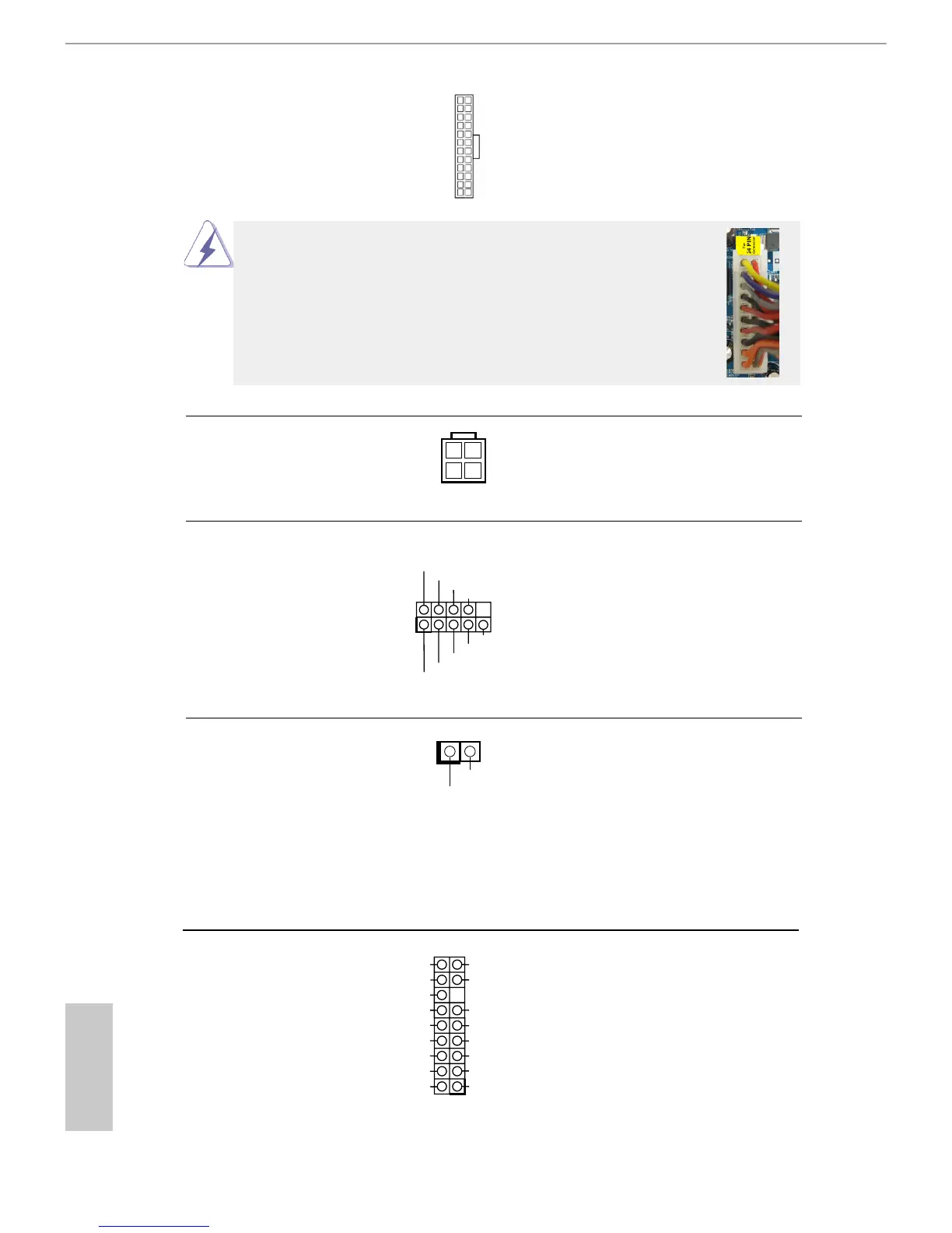
ATX Power Connector Please connect an ATX power
(24-pin ATXPWR1)
supply to this connector.
(see p.11 No. 5)
12
1
24
13
Though this motherboard provides 24-pin ATX power connector,
it can still work if you adopt a traditional 20-pin ATX power supply.
To use the 20-pin ATX power supply, please plug your power
supply along with Pin 1 and Pin 13.
20-Pin ATX Power Supply Installation
12
1
24
13
Serial port Header This COM1 header supports a
(9-pin COM1)
serial port module.
(see p.11 No. 18)
CCTS#1
RRTS#1
DDSR#1
DDTR#1
RRXD1
GND
TTXD1
DDCD#1
1
RRI#1
ATX 12V Power Connector Please connect an ATX 12V
(4-pin ATX12V1)
power supply to this connector.
(see p.11 No. 1)
Chassis Intrusion Header
(2-pin CI1)
(see p.11, No. 19)
This motherboard supports
CASE OPEN detection feature
that detects if the chassis
cover has been removed. This
feature requires a chassis with
chassis intrusion detection
design.
TPM Header
(17-pin TPMS1)
(see p.11, No. 4)
This connector supports Trust-
ed Platform Module (TPM)
system, which can securely
store keys, digital certicates,
passwords, and data. A TPM
system also helps enhance
network security, protects
digital identities, and ensures
platform integrity.
1
LFRAME#_L
TPM_RST#
LAD3_L
+3V
LAD0_L
+3VSB
GNDF_CLKRUN#
SERIRQ#
S_PWRDWN#
GND
LAD1_L
LAD2_L
 Loading...