32
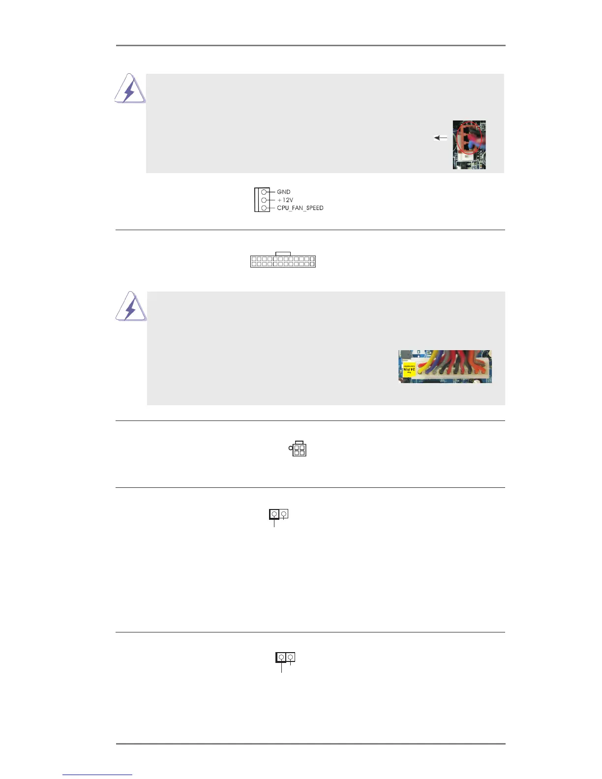
ATX Power Connector Please connect an ATX power
(24-pin ATXPWR1)
supply to this connector.
(see p.14 No. 2)
24 13
12 1
Though this motherboard provides 24-pin ATX power connector, it can still work if
you adopt a traditional 20-pin ATX power supply. To use the 20-pin ATX power
supply, please plug your power supply along with Pin 1 and Pin 13.
20-Pin ATX Power Supply Installation
ATX 12V Power Connector Please connect an ATX 12V
(4-pin ATX12V1)
power supply to this connector.
(see p.14, No. 21)
Chassis Intrusion Header This motherboard supports
(2-pin CI1)
CASE OPEN detection feature
(see p.14, No. 1)
that detects if the chassis cover
has been removed. This feature
requires a chassis with chassis
intrusion detection design.
1
Sig nal
GND
24 13
12 1
HDMI_SPDIF Header HDMI_SPDIF header, providing
(2-pin HDMI_SPDIF1)
SPDIF audio output to HDMI
(
see p.14 No. 23)
VGA card, allows the system to
connect HDMI Digital TV/
projector/LCD devices. Please
connect the HDMI_SPDIF
connector of HDMI VGA card to
this header.
SPD IFOUT
GND
1
Though this motherboard provides 4-Pin CPU fan (Quiet Fan) support, the 3-Pin
CPU fan still can work successfully even without the fan speed control function.
If you plan to connect the 3-Pin CPU fan to the CPU fan connector on this
motherboard, please connect it to Pin 1-3.
(3-pin CPU_FAN2)
(see p.14 No. 28)
Pin 1-3 Connected
3-Pin Fan Installation