Do you have a question about the ASROCK G41M-GS and is the answer not in the manual?
Lists all items included with the motherboard package.
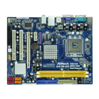
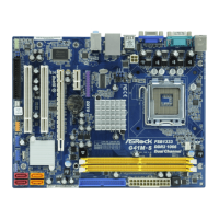
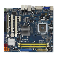
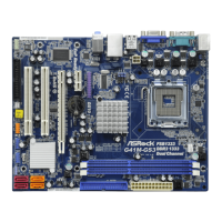
Details the motherboard's form factor and physical dimensions.
Lists supported CPU socket types and processor families.
Specifies the Northbridge and Southbridge chipsets used.
Details memory technology, slots, and maximum capacity.
Lists available PCI and PCI Express slots.
Describes the integrated graphics processor and DirectX support.
Specifies the onboard audio codec and its features.
Details the onboard LAN controller and its speed.
Lists all ports available on the rear I/O panel.
Lists all onboard headers and connectors for internal devices.
Highlights important BIOS features and capabilities.
Lists the software and drivers available on the support CD.
Describes unique ASRock technologies and features.
Lists hardware monitoring parameters like temperature and fan speed.
Lists compatible operating systems.
Lists relevant certifications like FCC and CE.
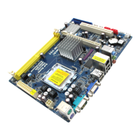
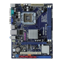
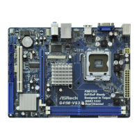
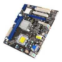
Identifies and describes each numbered component on the motherboard layout.
Identifies and describes each numbered port on the I/O panel.
Explains the meaning of the LED indicators on the LAN port.
Details the screw hole locations for motherboard mounting.
Lists essential precautions before installing components.
Provides an overview of the 775-pin CPU socket.
Step-by-step instructions for opening the CPU socket.
Instructions on how to correctly insert the CPU into the socket.
Precise steps for placing the CPU vertically into the socket.
Instructions for safely removing the CPU's Pick and Place cap.
Steps for closing the CPU socket after installation.
Instructions for applying thermal interface material.
Guides on correctly placing the heatsink onto the socket.
Steps for aligning and securing the heatsink fasteners.
Instructions for installing and locking the heatsink fasteners.
How to connect the CPU fan header to the motherboard.
Securing excess fan cables for safety.
Step-by-step guide for installing memory modules into slots.
How to unlock the DIMM slot retaining clips.
Aligning the memory module's notch with the slot.
Instructions for inserting the DIMM until clips lock.
Step-by-step guide for installing expansion cards.
Pre-installation safety check for power.
Removing the expansion slot bracket.
Aligning and inserting the expansion card into the slot.
Securing the installed expansion card to the chassis.
Configures standby power for PS/2 or USB wake-up events.
Resets system BIOS settings to default values.
Controls power consumption to meet EuP standard.
Details jumper settings for standard CPU and memory configurations.
Explains jumper adjustments for overclocking CPU frequencies.
Describes the floppy disk drive connector.
Details the primary IDE connector for hard drives or optical drives.
Lists and describes the Serial ATAII connectors.
Explains how to connect SATA data cables.
Details connecting SATA power cables.
Describes the onboard USB 2.0 headers for front panel ports.
Details the header for connecting a parallel printer port.
Explains connecting front panel audio devices.
Connects front panel power buttons, LEDs, and reset switches.
Connects the internal chassis speaker.
Connects a chassis fan to the motherboard.
Connects the CPU fan to the motherboard.
Describes the 24-pin ATX power connector for system power.
Explains the ATX 12V connector for CPU power supply.
Jumper settings for Western Digital SATA hard disks.
Jumper settings for Samsung SATA hard disks.
Information on configuring Hitachi SATA hard disks.
Procedure for installing SATA/SATAII hard disks into chassis.
Connecting the SATA power cable to the drive.
Connecting one end of the SATA data cable to the motherboard.
Connecting the other end of the SATA data cable to the drive.
Explains how to use the BIOS Setup Utility.
Describes the main menu bar selections in the BIOS.
Explains the function of navigation keys within the BIOS.
How to save configuration changes and exit the BIOS.
Loads default BIOS settings for all options.
Loads performance-oriented default BIOS settings.
Loads power-saving default BIOS settings.
Utility for updating the system BIOS.
Loads optimized CPU overclocking settings for specific CPUs.
Selects the mode for CPU overclocking.
Adjusts the CPU core frequency.
Adjusts the PCI Express bus frequency.
Enables or disables Boot Failure Guard.
Manages spread spectrum for system stability.
Displays if the CPU multiplier is locked or unlocked.
Allows changing the CPU ratio value when unlocked.
Supports processor's C1 power state for energy saving.
Enables Intel Virtualization Technology.
Enables internal thermal control for the CPU.
Provides protection against malicious code execution.
Enables Intel Hyper-Threading Technology.
Adjusts the CPU clock duty cycle for power saving.
Enables Intel SpeedStep technology for power saving.
Enables or disables memory remapping for PCI devices.
Automatically detects or allows manual setting of DRAM frequency.
Enhances memory compatibility tolerance.
Adjusts DRAM CAS Latency timing.
Controls DRAM Row Column Delay timing.
Controls DRAM Row Precharge timing.
Controls DRAM Row Active time.
Controls DRAM Refresh Cycle timing.
Controls DRAM Write Recovery timing.
Controls DRAM Write to Read Delay timing.
Controls DRAM Row to Row Delay timing.
Controls DRAM Read to Precharge Delay timing.
Controls DRAM Channel 0 RCOMP ODT.
Controls DRAM Channel 1 RCOMP ODT.
Controls DRAM Channel 0 Read Delay timing.
Controls DRAM Channel 1 Read Delay timing.
Controls DRAM Channel 0 Read Delay Phase Adjust.
Controls DRAM Channel 1 Read Delay Phase Adjust.
Enables or disables flex mode operation feature.
Controls DRAM Channel 0 GO (Data).
Controls DRAM Channel 0 G1 (Command).
Controls DRAM Channel 0 G2 (Control1).
Controls DRAM Channel 0 G3 (Control2).
Controls DRAM Channel 0 G4 (Clocks1).
Controls DRAM Channel 0 G5 (Clocks2).
Controls DRAM Channel 1 G0 (Data).
Controls DRAM Channel 1 G1 (Command).
Controls DRAM Channel 1 G2 (Control1).
Controls DRAM Channel 1 G3 (Control2).
Controls DRAM Channel 1 G4 (Clocks1).
Controls DRAM Channel 1 G5 (Clocks2).
Controls DRAM Channel 0 CLKSETO SKEW.
Controls DRAM Channel 0 CLKSET1 SKEW.
Controls DRAM Channel 0 CMD SKEW.
Controls DRAM Channel 0 CTRLO SKEW.
Controls DRAM Channel 0 CTRL1 SKEW.
Controls DRAM Channel 0 CTRL2 SKEW.
Controls DRAM Channel 0 CTRL3 SKEW.
Controls DRAM Channel 1 CMD SKEW.
Controls DRAM Channel 1 CTRLO SKEW.
Controls DRAM Channel 1 CTRL1 SKEW.
Controls DRAM Channel 1 CTRL2 SKEW.
Controls DRAM Channel 1 CTRL3 SKEW.
Selects the primary boot graphic adapter.
Sets the amount of shared memory for graphics.
Adjusts PAVP mode for premium content playback.
Selects the DVMT mode for graphics memory allocation.
Adjusts shared memory size for DVMT mode.
Enables or disables the onboard HD Audio feature.
Enables or disables the onboard HD Audio Front Panel.
Enables or disables the onboard LAN feature.
Selects CPU voltage settings.
Selects the DRAM voltage.
Selects the Northbridge (NB) voltage.
Selects the Southbridge (SB) voltage.
Selects the VTT voltage.
Selects the GLTREF voltage.
Enables Intelligent Energy Saver for power savings.
Selects whether to auto-detect or disable Suspend-to-RAM.
Reposts video on Suspend to RAM resume.
Enables or disables the Check Ready Bit feature.
Sets the system power state after AC/Power loss.
Enables or disables Ring-In signals to power on the system.
Enables or disables PCI devices to power on the system.
Enables or disables PS/2 keyboard to power on the system.
Enables or disables RTC alarm to power on the system.
Sets ATA/IDE configuration for legacy or native OS.
Selects device combinations between SATA and IDE.
Configures the type of IDE device connected.
Selects LBA/Large mode for hard disks over 512MB.
Enhances hard disk performance via block transfer.
Sets PIO mode to optimize hard disk timing.
Improves transfer speed and data-integrity for IDE devices.
Enables or disables S.M.A.R.T. feature.
Enables 32-bit access for IDE hard disk transfer rate.
Sets the PCI latency timer for expansion cards.
Enables or disables the PCI IDE BusMaster feature.
Enables or disables the onboard floppy drive controller.
Sets the address for the onboard serial port.
Sets the address for the onboard parallel port.
Sets the operation mode of the parallel port.
Sets the EPP version for parallel port.
Sets the ECP mode DMA channel.
Sets the IRQ for the parallel port.
Enables or disables the use of the USB controller.
Enables or disables USB 2.0 support.
Selects legacy support for USB devices.
Controls CPU fan speed based on temperature.
Sets the target CPU temperature for fan control.
Sets the target fan speed for the CPU cooler.
Configures boot device order and display options.
Enables or disables the display of the OEM Logo.
Controls display of AddOn ROM information during boot.
Selects the logo displayed on the POST screen.
Enables or disables booting from the onboard LAN.
Sets the Numeric Lock state after boot-up.
Installs or changes the supervisor password.
Installs or changes the user password.
Saves configuration changes and exits the BIOS utility.
Exits the BIOS utility without saving any changes.
Discards all current unsaved changes.
Guidance for installing supported operating systems.
Details the contents of the motherboard support CD.
Instructions on how to run the support CD.
Describes the Drivers Menu on the support CD.
Describes the Utilities Menu on the support CD.
Provides contact information for ASRock.
| Number of memory slots | 2 |
|---|---|
| Maximum internal memory | 8 GB |
| Processor socket | LGA 775 (Socket T) |
| Processor manufacturer | Intel |
| Compatible processor series | Intel® Celeron® |
| CPU fan connector | Yes |
| Number of SATA connectors | 4 |
| Number of Parallel ATA connectors | 1 |
| Headphone outputs | 3 |
| USB 2.0 ports quantity | USB 2.0 ports have a data transmission speed of 480 Mbps, and are backwards compatible with USB 1.1 ports. You can connect all kinds of peripheral devices to them. |
| Firewire (IEEE 1394) ports | 0 |
| Audio chip | Realtek ALC662 |
| Certification | FCC, CE, EuP Ready |
| Power source type | ATX |
| Audio output channels | 5.1 channels |
| Motherboard form factor | micro ATX |
| Compatible operating systems | Windows 2000 / XP / XP 64-bit / Vista / Vista 64-bit |
| BIOS type | AMI |
| Maximum graphics card memory | 352 MB |
| Parallel processing technology support | Not supported |
| LAN controller | Realtek RTL8111D(L) |
| Networking features | 10/100/1000 Mb/s |