1818
1818
18
ASRock P45DE Motherboard
EnglishEnglish
EnglishEnglish
English
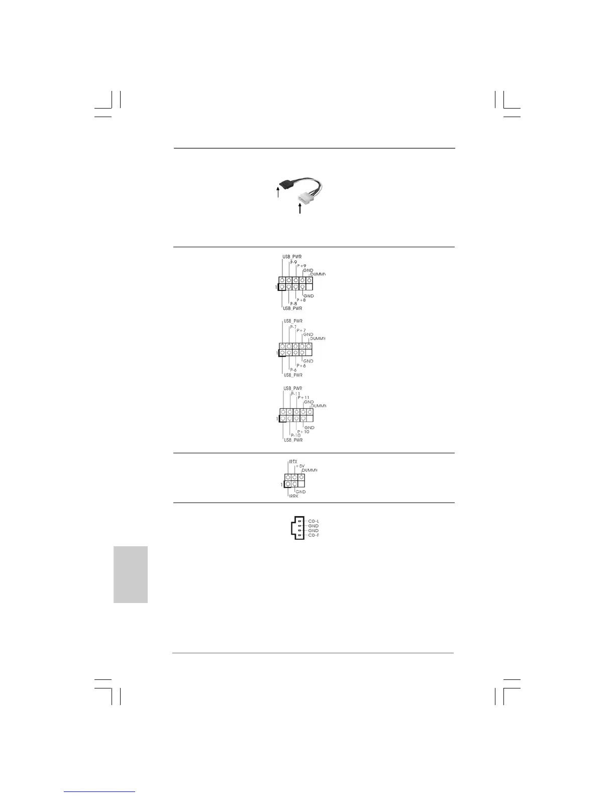
Serial ATA (SATA) Please connect the black end of
Power Cable SATA power cable to the power
(Optional) connector on each drive. Then
connect the white end of SATA
power cable to the power
connector of the power supply.
connect to
the power
supply
connect to the SATA
HDD power connector
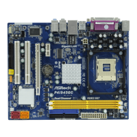
Internal Audio Connectors This connector allows you
(4-pin CD1) to receive stereo audio input
(see p.2 No. 34) from sound sources such as
a CD-ROM, DVD-ROM, TV
tuner card, or MPEG card.
Infrared Module Header This header supports an
(5-pin IR1) optional wireless transmitting
(see p.2 No. 26) and receiving infrared module.
CD1
USB 2.0 Headers Besides six default USB 2.0
(9-pin USB8_9) ports on the I/O panel, there are
(see p.2 No. 19) three USB 2.0 headers on this
motherboard. Each USB 2.0
header can support two USB
2.0 ports.
(9-pin USB6_7)
(see p.2 No. 18)
(9-pin USB/WIFI)
(see p.2 No. 29)