23
ASRock P67 Transformer Motherboard
English
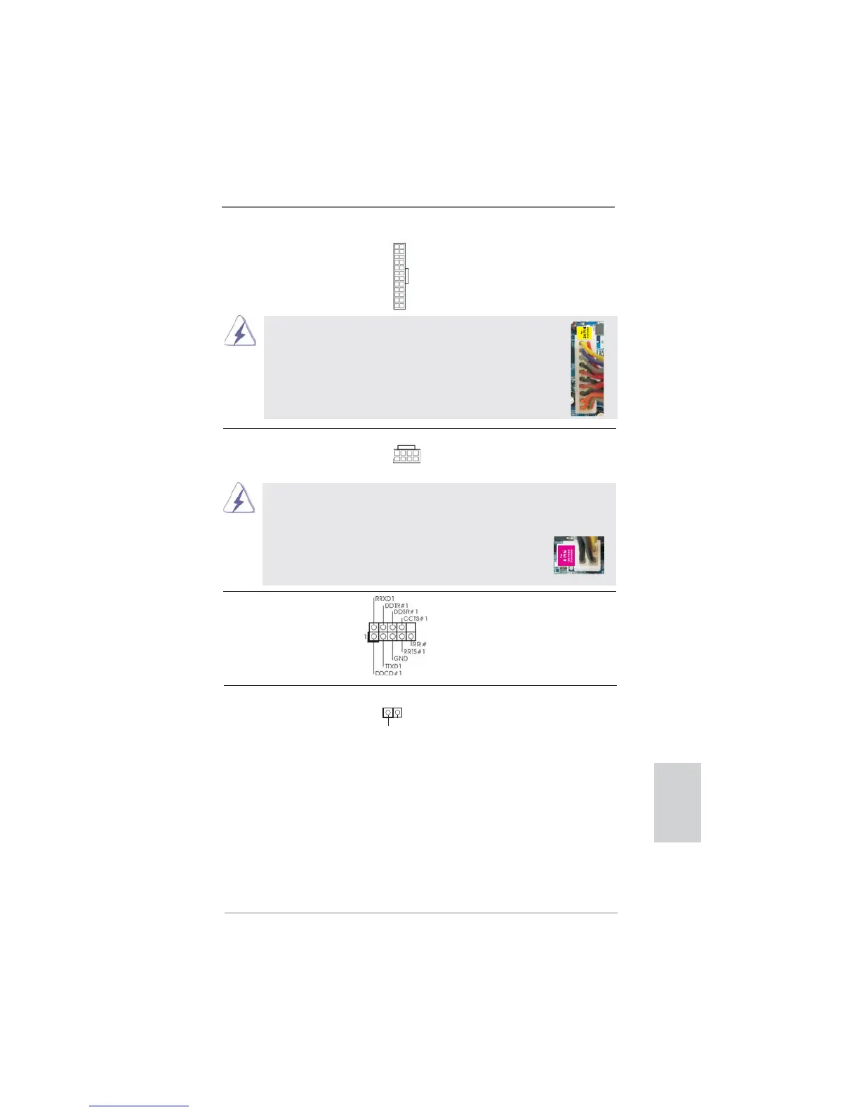
ATX Power Connector Please connect an ATX power
(24-pin ATXPWR1)
supply to this connector.
(see p.2 No. 6)
12
1
24
13
20-Pin ATX Power Supply Installation
Though this motherboard provides 24-pin ATX power connector,
it can still work if you adopt a traditional 20-pin ATX power supply.
To use the 20-pin ATX power supply, please plug your
power supply along with Pin 1 and Pin 13.
12
1
24
13
ATX 12V Power Connector Please connect an ATX 12V
(8-pin ATX12V1)
power supply to this connector.
(see p.2 No. 1)
4-Pin ATX 12V Power Supply Installation
Though this motherboard provides 8-pin ATX 12V power connector, it can still work
if you adopt a traditional 4-pin ATX 12V power supply. To use the 4-pin ATX power
supply, please plug your power supply along with Pin 1 and Pin 5.
8 5
4 1
8 5
4 1
HDMI_SPDIF Header HDMI_SPDIF header, providing
(2-pin HDMI_SPDIF1)
SPDIF audio output to HDMI
(see p.2 No. 31)
VGA card, allows the system to
connect HDMI Digital TV/
projector/LCD devices. Please
connect the HDMI_SPDIF
connector of HDMI VGA card to
this header.
SPDIFOUT
GND
1
Serial port Header This COM1 header supports a
(9-pin COM1)
serial port module.
(see p.2 No. 30)
 Loading...