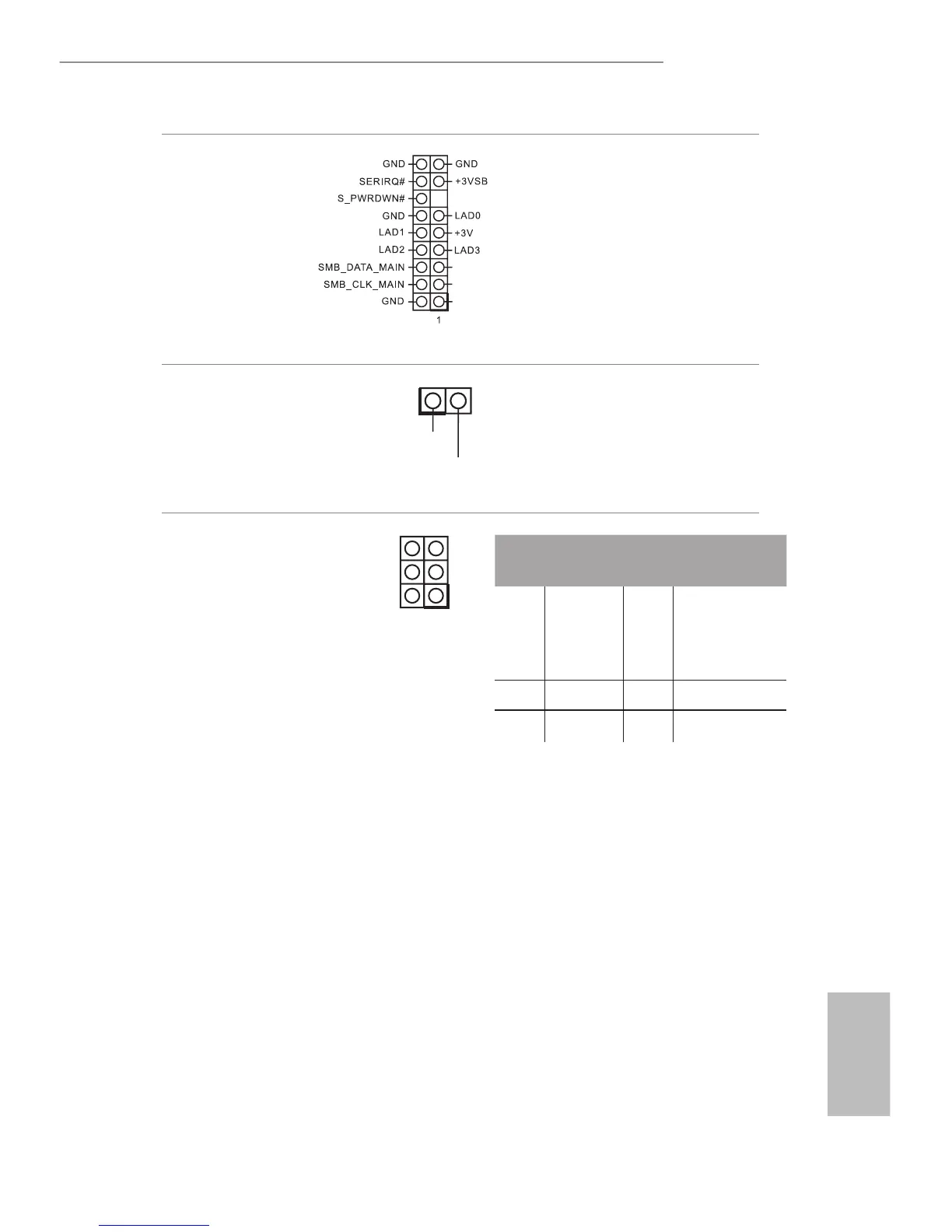
TPM Header
(17-pin TPMS1)
(see p.1, No. 19)
is connector supports Trusted
Platform Module (TPM) system,
which can securely store keys,
digital certicates, passwords,
and data. A TPM system also
helps enhance network security,
protects digital identities, and
ensures platform integrity.
Monitor Switch Header
(2-pin MONITOR_
SWITCH1)
(see p.1, No. 5)
1
PWRDN
is header can be used to
connect a switch that turns on/
o the LVDS panel display’s
backlight.
Digital Input / Output Pin
Header
(10-pin JGPIO1)
(see p.1, No. 23)
1
PCIRST#
FRAME
PCICLK
PIN
Signal
Name
PIN Signal Name
6 GND 5
JGPIOPWR
(use JGPIO_
PWR1 to
congure)
4 GPIO4 3 GPIO3
2 GPIO2 1 GPIO1
 Loading...