English
16
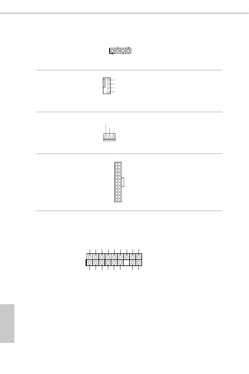
Chassis Speaker Header
(4-pin SPEAK ER1)
(see p.5, No. 8)
Please connect the chassis
speaker to this header.
Chassis Fan Connector
(4-pin CHA_FAN1)
(see p.5, No. 3)
Please connect fan cables
to the fan connectors and
match the black wire to
the ground pin.
CPU Fan Connector
(3-pin CPU_FAN1)
(see p.5, No. 9)
Please connect fan cables
to the fan connectors and
match the black wire to
the ground pin.
ATX Power Connector
(24-pin ATXPWR1)
(see p.5, No. 4)
is motherboard pro-
vides a 24-pin ATX power
connector. To use a 20-pin
ATX power supply, please
plug it along Pin 1 and Pin
13.
TPM Header
(17-pin TPMS1)
(see p.5, No. 12)
is connector supports
Trusted Platform Module
(TPM) system, which can
securely store keys, digital
certicates, passwords,
and data. A TPM system
also helps enhance
network security, protects
digital identities, and
ensures platform integrity.
+5V
DUMMY
DUMMY
+12V
CHA_FAN_SPEED
FAN_SPEED_CONTR
D
CPU_FA
FAN_VOLTAGE
12
1
24
13
GN D
SMB_DATA_MAIN
LAD 2
LAD 1
GN D
S_PWRDWN #
SERIRQ #
GN
D
P CICLK
P CIRST #
LAD 3
+3V
LAD 0
+3VS B
GN D
FRAM E
SMB_CLK_MAIN
 Loading...