Do you have a question about the ASROCK Z790 Steel Legend WiFi and is the answer not in the manual?
| Processor socket | LGA 1700 |
|---|---|
| Processor manufacturer | Intel |
| Compatible processor series | Intel Core i5, Intel Core i7, Intel Core i9 |
| Maximum number of SMP processors | 1 |
| Non-ECC | Yes |
| Memory channels | Dual-channel |
| Memory slots type | DIMM |
| Number of memory slots | 4 |
| Supported memory types | DDR5-SDRAM |
| Maximum internal memory | 128 GB |
| RAID levels | 0, 1, 5, 10 |
| Supported storage drive types | HDD & SSD |
| Supported storage drive interfaces | M.2, SATA III |
| Parallel processing technology support | - |
| USB 2.0 connectors | 2 |
| Number of SATA III connectors | 8 |
| DisplayPort version | 1.4 |
| USB 2.0 ports quantity | 0 |
| LAN controller | Dragon RTL8125BG |
| Wi-Fi standards | 802.11a, 802.11g, Wi-Fi 4 (802.11n), Wi-Fi 5 (802.11ac), Wi-Fi 6E (802.11ax) |
| Top Wi-Fi standard | Wi-Fi 6E (802.11ax) |
| Ethernet interface type | 2.5 Gigabit Ethernet |
| Audio chip | Realtek ALC897 |
| Component for | PC |
| Motherboard chipset | Intel Z790 |
| Audio output channels | 7.1 channels |
| Motherboard form factor | ATX |
| Windows operating systems supported | Windows 10 x64, Windows 11 x64 |
| BIOS type | UEFI AMI |
| BIOS memory size | 256 Mbit |
| Depth | 244 mm |
|---|---|
| Width | 305 mm |
Lists items included with the ASRock Z790 Steel Legend WiFi motherboard, such as the manual and accessories.
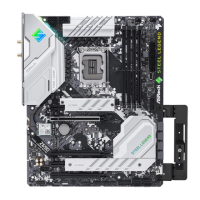
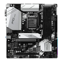
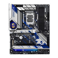
Details the technical specifications of the motherboard, including CPU, memory, and expansion slots.
Outlines essential safety measures and handling guidelines before installing motherboard components.
Provides step-by-step instructions for safely installing the CPU into the motherboard socket.
Details the procedure for mounting the CPU cooler, including thermal paste application.
Explains how to properly install DDR5 memory modules into the motherboard slots for dual-channel configuration.
Guides on connecting the front panel wires from the PC case to the motherboard header for power, reset, and LEDs.
Instructs on how to securely mount the motherboard inside the computer chassis.
Explains the process of connecting SATA data and power cables to storage devices like HDDs and SSDs.
Provides instructions for inserting a graphics card into the PCIe slot and securing it.
Illustrates how to connect external devices like monitors, keyboards, and mice to the motherboard's I/O panel.
Details the connection of the 24-pin ATX and 8-pin CPU power connectors from the power supply to the motherboard.
Guides users on the correct sequence to power on the computer after assembly.
Explains how to configure motherboard jumpers, specifically the Clear CMOS jumper.
Describes the function and pin assignments of various onboard headers like System Panel, Power LED, and USB headers.
Details the connection of the chassis power LED and speaker to the SPK_PLED1 header.
Illustrates the location and orientation of the eight SATA3 connectors for storage devices.
Explains the pin configuration for the two USB 2.0 headers on the motherboard.
Details the pin assignments for the two USB 3.2 Gen1 headers, each supporting two ports.
Describes the header for connecting a USB 3.2 Gen2x2 module for front panel Type-C ports.
Explains the connection of front panel audio devices to the HD_AUDIO1 header.
Details the five 4-pin fan connectors for chassis and water cooling, including pinouts.
Describes the 4-pin CPU fan header (CPU_FAN1) and its pinout for connecting fans.
Explains the 4-pin CPU/Water Pump fan header (CPU_FAN2/WP) and its pinout for cooling solutions.
Details the 24-pin ATX power connector (ATXPWR1) and its connection for system power.
Describes the two 8-pin ATX 12V power connectors (ATX12V1, ATX12V2) for CPU power.
Explains the SPI TPM header for connecting a Trusted Platform Module for enhanced security.
Details the Thunderbolt AIC connector (TB1) for adding Thunderbolt capabilities via an add-in card.
Describes the RGB LED header (RGB_LED1) for connecting RGB LED extension cables for lighting effects.
Explains the Addressable LED headers (ADDR_LED1, ADDR_LED2, ADDR_LED3) for addressable RGB LED strips.
Explains the Post Status Checker (PSC) LEDs that diagnose system boot status and component functionality.
Provides instructions for installing M.2 SSDs into the M2_1 and M2_2 slots, including standoff placement.
Details the installation process for M.2 SSDs in M2_3 and M2_4 slots, covering different module types.
Guides on installing M.2 SSDs into the M2_5 slot, specifying standoff and module compatibility.
Explains how to adjust the screen brightness for eDP panels within the Windows operating system.