19
R
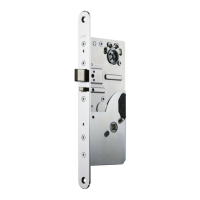
MANIPULATION PROTECTION COVER Fig. A ENGLISH
1. Bend the corners of manipulation protection cover slightly.
2. Remove the cover.
3. Before installing the manipulation protection cover back in its place, bend the sides of the
cover lightly together.
INSTALLATION OF CABLE COVER Fig. B
The cable cover has to be placed into the lock case as shown in fi g. B.
CHANGING THE OPENING DIRECTION OF THE TRIGGER BOLT Fig. C
Tool: 2 mm Allen key
1. Loosen the fi xing screw of the trigger bolt.
2. Pull the trigger bolt out and turn it round.
3. Put the trigger bolt back to place.
4. Tighten the fi xing screw.
CHANGING THE OPENING DIRECTION OF THE LATCH BOLT Fig. C
Tool: 2.5 mm Allen key
5. Check that the latch bolt is not deadlocked.
6. Remove the fi xing screw of the latch bolt.
7. Pull the latch bolt out and turn it round.
8. Put the latch bolt back to place.
9. Insert the fi xing screw to the other side of the lock case and tighten it.
CHANGING THE BOLT THROW (Factory setting: 20 mm) (EL590)
Fig. D, Fig. E
Tool: 2.5 mm Allen key
Bolt throw change from 20 mm to 14 mm:
Check that the latch bolt is not deadlocked.
1. Remove the latch bolt fi xing screw.
2. Push the trigger bolt in and at the same time push the latch bolt in momentarily.
3. Check that the tailpiece is in deadlocked position.
4. Tighten the latch bolt fi xing screw.
5. Remove the allen screw shown in fi g. D.
6. Check the function of the bolt.
Bolt throw change from 14 mm to 20 mm:
1. Remove the latch bolt fi xing screw.
2. Turn the tailpiece mechanism in, so that the lock is not deadlocked (do not press the trig-
ger bolt).
3. Check that the tailpiece is in normal position (not deadlocked) as shown in fi g. E.
4. Tighten the latch bolt fi xing screw.
5. Insert and tighten the allen screw M3 x 3 DIN912 as shown in fi g. E.
6. Check the function of the bolt.
 Loading...