20
R
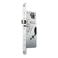
ADJUSTABLE DELAY SETTINGS (Factory setting: 1 sec) Fig. F ENGLISH
1.Remove the Torx screw shown in fi g. F.
2. Make the adjustment:
- The delay extends by turning the adjustment screw anticlockwise with the special screw-
driver which is supplied with the lock case.
3. Install and tighten the Torx screw.
Note! Do not use too much force.
HANDLE FUNCTION SETTINGS (Factory setting: mechanical) (EL590) Fig. G
Tool: 2,5 mm allen key
1. Mechanical -> Electrically controlled
Remove the allen screw shown in Fig. G.
2. Electrically controlled -> Mechanical
Install and tighten allen screw M3 x 3 DIN912 shown in Fig. G.
Note! Check the local exit door regulations. When the allen screw is removed, lock case no
longer complies to EN179.
INSTALLATION OF THE CYLINDER/ THUMBTURN MONITORING SWITCH
Fig. H
Install the switch 950885 into the hole in the monitoring side of the lock case so that the fl at
side of the switch is towards the lock case (H1)/ the lock case cover (H2).
Connect the wires to the lock cable.
MAINTENANCE Fig. I
Manipulation cover
Remove the cover as shown in Fig. A:
1. Bend the corners of manipulation protection cover slightly.
2. Remove the cover.
3. Before installing the manipulation protection cover back in its place, bend the sides of the
cover lightly together.
Removal of the cable plug
Tool: Pliers 8651130 (available as an accessory)
1. Lift the rubber cable cover from the lock case (I1).
2. Using pliers hold the plug as shown in I2 and lift the cable plug upright.
!
!
!
 Loading...