2. Power Mode
A. Installation
In this configuration, the device is not energized when locked. When energized with a 24 volt input, the pushbar and latch(es) will retract and
remain in the retracted position until power is removed. Power is typically applied through a relay triggered by an access control device. For
installations using the onboard timer circuit, refer to Section 3 Timer Mode.
Rail retracts when power is applied and releases when power is removed.
1. Mount 6000 Series exit device using mechanical installation instruction sheet(s) provided.
NOTE:
Ensure proper mechanical function before attempting electrical retraction:
Verify the pushbar can be fully depressed and the latch is fully retracted.
On vertical rod devices, verify latch bolts do not enter hold-back position until pushbar is fully depressed.
Adjust device mechanically as required, before applying power.
2. Connect the ElectroLynx harness in the door. See Figure 8.
Figure 9 - Non-ElectroLynx Power Mode Wiring MELR Wires with ElectroLynx Connector Removed
* “S” NO/NC (Normally Open/Normally Closed) is selectable on controller (refer to “S” DIP switch instructions in Section 3). Factory present
is NO.
3. Plug the 8-pin ElectroLynx connector from the pushbar into the 3” ElectroLynx harness or splice into non-ElectroLynx harness. See
Figure 9.
3" ElectroLynx Harness with 8-pin
Connector (purchased separately)
1 - Black (MELR 0VDC)
2 - Red (MELR +24VDC)
5 - Orange ( "S" NC/NO)*
7 - Brown ( "B" NO)
8 - Yellow ( "B" NC)
3 - White ("S" C)
6 - Blue ( "B" C)
4 - Green (EG)
4-pin F
8-pin F
8-pin M8-pin M
Not Used
1 - Black (MELR 0VDC)
Loose wires with no termination
connected with wire nuts
2 - Red (MELR +24VDC)
5 - Orange ( "S" NC/NO)*
7 - Brown ( "B" NO)
8 - Yellow ( "B" NC)
3 - White ("S" C)
6 - Blue ( "B" C)
4 - Green (EG)
4-pin F
Not Used
Non-ElectroLynx Electric Hinge
Figure 8 - Typical ElectroLynx Power Mode Wiring
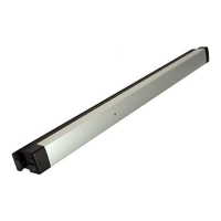
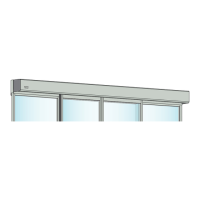
6000 Series MELR
Exit Devices
Installation Instructions
9
80-8150-0077-000 04/24
Copyright © 2017, 2023, 2024, ASSA ABLOY ACCENTRA™ Access and Egress Hardware Group, Inc. All rights reserved. Reproduction
in whole or in part without the express written permission of ASSA ABLOY Access and Egress Hardware Group, Inc. is prohibited.
1-855-577-5078 Ext. 2 • www.accentra-assaabloy.com
 Loading...