5/8
(16)
REF.
DOOR
FRAME
ADAPTER
PLATE
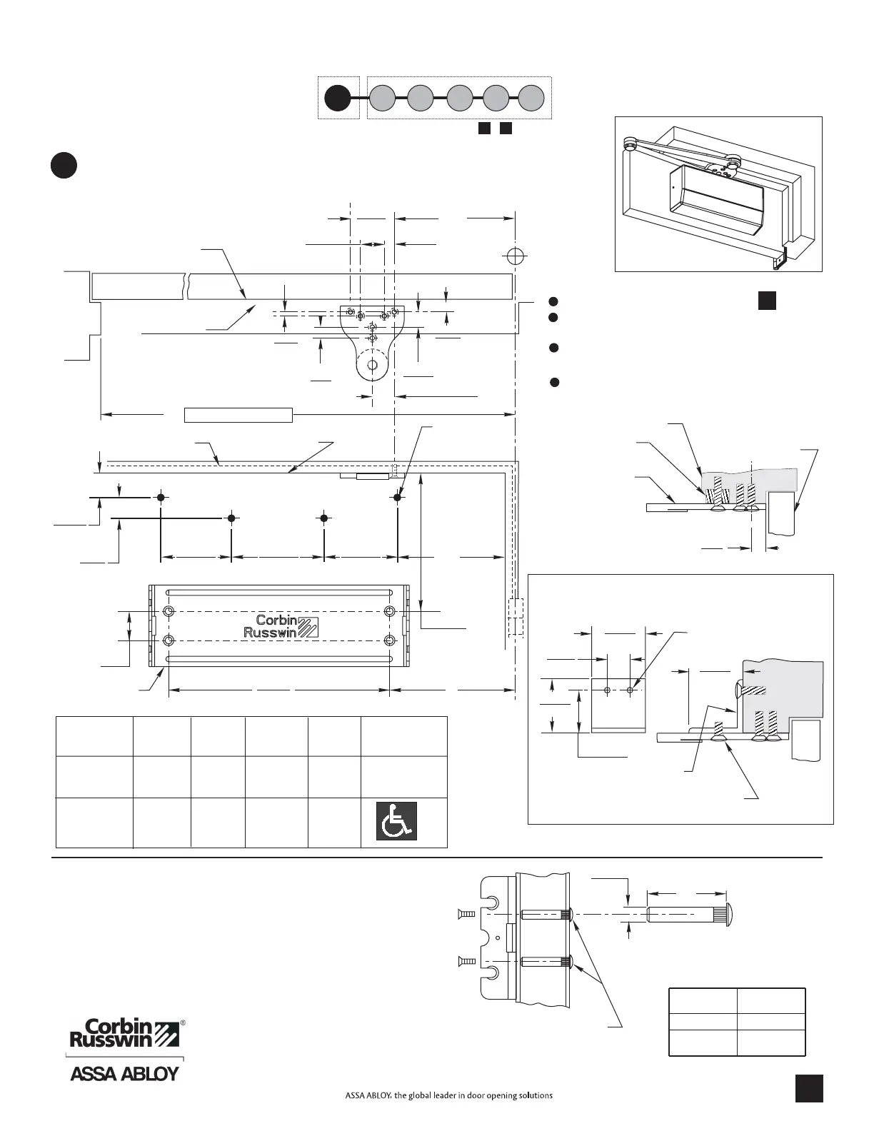
NOTES:
Check hand of door, see page .
Right Hand Application Shown. Left Hand
Opposite.
Dimensions given in inches (mm). Do Not
Scale Drawing.
Closer must be installed inatrue horizontal
plane to ensure proper closer performance.
80-9380-8002-152 Rev. 07/09
SPACER BLOCK
(When required)
2
(50.8)
2
(50.8)
2
(50.8)
1
(25.4)
1-1/2
(38.1)
SEE MOUNTING SCREW
SPECIFICATIONS
NOTE: ANGLE SUPPORT MUST BE
DRILLED AND TAPPED IN THE FIELD
447F14
DOOR
FRAME
MAXIMUM
OPENING
A
dp
B
Application
M85 OPTION 447F14
ANGLE SUPPORT BRACKET
90°
180°
7-1/2
(191)
3-1/2
(89)
11-5/8
(295)
7-5/8
(194)
NON
A.D.A.
C
27-3/4
(705)
23-5/8
(600)
Mark Door and Jamb (for QUIK-INSTALL bracket and arm bracket)
Use template and dimensions charted.
®
Template
5/8
(16)
FRAME STOP
TOP OF DOOR
C
L
HINGE
OR
PIVOT
DOOR
FRAME STOP
2-3/4
(70)
5/8
(16)
1-1/2
(38.1)
1/4
(6.35)
B
A
C
TYP.
15/16
(23.8)
3/4
(19)
1-3/8
(35)
Minimum Clearance
QUIK-INSTALL
BRACKET 754F18
10
(254)
1
(25.4)
3-1/16
(77.8)
1/2
(12.7)
A
dp
3
(76.2)
4-3/4
(120.7)
3
(76.2)
3/8
(9.5)
Parallel Arm
2
1
D
C
E
B
This P age Next Page ( , )
3
A F
A
DC8210 x A3 HD Parallel Arm Installation Instructions
Quick Install
Bracket
Drop Plate Soffit Bracket
A
7-7/8
(200)
3-7/8
(98)
Clearance
DROP PLATE
Mounting Holes (4)
754F25
L
3/8
(10)
1/4-20 THREAD
Drill thru 9/32 (7) Enlarge to
3/8 (10) Dia. This Side Only
(4 Places)
MOUNTING SCREW SPECIFICATIONS
ARM AND BRACKETQUIK-INSTALL
}
or
{
Sex nuts, furnished
when ordered
#12-14 self-drilling screw.
1/8 (3) diameter pilot hole
required for Wood
Applications.
DOOR
THICKNESS
SEX NUT
LENGTH “L”
1-3/8 (35)
1-3/4 (44)
& OVER
1-9/32 (33)
1-21/32 (42)
4
 Loading...