13
Delayed Egress
Installation Instructions
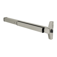
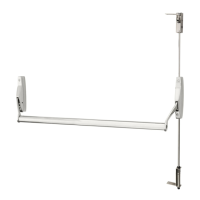
ED4000, ED5000 Series Exit Device
FM209 10/20
Copyright © 2006, 2010, 2018, 2020 ASSA ABLOY Access and Egress Hardware Group, Inc. All rights reserved. Reproduction in whole or
in part without the express written permission of ASSA ABLOY Access and Egress Hardware Group, Inc. is prohibited.
For installation assistance contact Corbin Russwin
1-800-543-3658 • techsupport.corbinrusswin@assaabloy.com
Note:
New wiring shown.
Items followed by *
indicate NEW PCBA
wiring OR NEW
DEVICE wiring that
differs from Legacy
wiring. Pluggable
4-pin connections
from Device Harness
to Main Harness is
for new QC12 hinge
wiring method.
QC12 Hinge -
Wiring Options
Wiring to 8-pin and
4-pin connectors are
REQUIRED (12 wires
max)
- If external DPS
wiring is REQUIRED
(Set PCBA Dip
Switch S2-7 OFF)
- If LBM, Trim Mon-
itor, OR Electrified
Trim Options are
REQUIRED.
10 ElectroLynx Wiring Options Overview with QC12 Hinge
Refer to Figure 7 for M93 Monitor - Trim Actuated SPDT Switch wiring.
NOTE:
• Switch wiring max load: 2A @28VDC.
• Wire must be protected from abrasion.
• For use with Class II circuits only.
• For ElectroLynx QC12 Hinge Connector System: Follow Sections 11, 12, and 13 wiring instructions.
• For non-ElectroLynx door:
Remove connector at end of exit device and connect to incoming wires from power source using
wire nuts, butt splices, etc. See Section 14 for hole locations and sizes.
Figure 7
After routing two
wires from ET
through the chassis
and the wire chan-
nel in back of rail
then Install Molex
Female 4-pin con-
nector (supplied)
onto pre-crimped
female terminals on-
toBlack wire pin 4-1,
Red wire pin 4-2
 Loading...