15
Delayed Egress
Installation Instructions
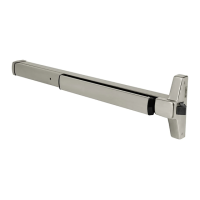
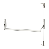
ED4000, ED5000 Series Exit Device
FM209 10/20
Copyright © 2006, 2010, 2018, 2020 ASSA ABLOY Access and Egress Hardware Group, Inc. All rights reserved. Reproduction in whole or
in part without the express written permission of ASSA ABLOY Access and Egress Hardware Group, Inc. is prohibited.
For installation assistance contact Corbin Russwin
1-800-543-3658 • techsupport.corbinrusswin@assaabloy.com
12 ElectroLynx Wiring Deed with Electrifi ed Trim (ET) Option and QC12 Hinge
QC12 Hinge - Field Wiring
Options
Wiring to 8-pin and 4-pin
connectors is REQUIRED
(12 wires max).
• If external DPS wiring
is NOT REQUIRED, set
PCBA Dip Switch S2-7
ON.
• If external DPS wiring
is REQUIRED, set PCBA
Dip Switch S2-7 OFF.
Supplied with DEED when ordered Fail Safe or
Fail Secure Electrifi ed Trim (ET)
*Requires field to route two wires from ET through
the chassis and the wire channel in back of rail then
install loose Molex Female 4-pin(*4F) connector
(supplied) onto pre-crimped female terminals onto
Black wire pin 4-1, Red wire pin 4-2.
9903 Electrified Trim (ET) (SAF)
Fail Safe
Or
9905 Electrified Trim (ET) (SEC)
Fail Secure
 Loading...