18
Delayed Egress
Installation Instructions
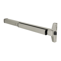
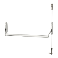
ED4000, ED5000 Series Exit Device
FM209 10/20
Copyright © 2006, 2010, 2018, 2020 ASSA ABLOY Access and Egress Hardware Group, Inc. All rights reserved. Reproduction in whole or
in part without the express written permission of ASSA ABLOY Access and Egress Hardware Group, Inc. is prohibited.
For installation assistance contact Corbin Russwin
1-800-543-3658 • techsupport.corbinrusswin@assaabloy.com
15 Wiring Diagram - Single Door Exit Only
Operation:
Mechanical trim can be added for entry. Ingress by trim without touching device push bar rim will not
affect alarm if a door position switch is not being used. Refer to DPS wiring if necessary.
Figure 9
To NC
Fire Alarm
Contacts
120 VAC
Securitron
BPS
Po wer
Supply
Wire
Transfer
Hinge
Connector
J2
(Device)
QC8
(-)
+24VDC
*Connect to EGND
*Connect to EGND
(-)
+24VDC
ALR NO/NC
BLU
EGND ORG
QC8
*Connect EGND within
BPS Power Supply or
Local Building Ground
16 Wiring Diagram - Single Door With Remote Inputs & Monitoring Outputs
Operation:
Monitoring: Red LED indicates device is armed and secure. Activating device will sound alarm. (Figure 10)
Green LED will illuminate after 15 seconds. Device will release for exit (unsecure).
NOTE: If dry contacts are needed for signaling or monitoring, a 24VDC relay is recommended.
Figure 10
 Loading...