25
Delayed Egress
Installation Instructions
FM209 10/20
Copyright © 2006, 2010, 2018, 2020 ASSA ABLOY Access and Egress Hardware Group, Inc. All rights reserved. Reproduction in whole
or in part without the express written permission of ASSA ABLOY Access and Egress Hardware Group, Inc. is prohibited.
For installation assistance contact Corbin Russwin
1-800-543-3658 • techsupport.corbinrusswin@assaabloy.com
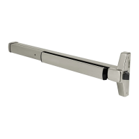
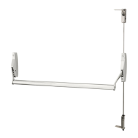
ED4000, ED5000 Series Exit Device
25 Appendix: Legacy Boards
J2
Connector
J1
Connector
J2
Connector
J1
Connector
To Device; F actory Wired
To Device; F actory Wired
Blac k
Red
White
Blue
Brown
Orange
Ye llow
Violet
Negative
Positive
Remote Reset
Remote Bypass
Secure Rel ayOutput (NO)
Secure Relay Output (NC)
Alarm Relay Output (NO )
Alarm Relay Output (NC)
Blac k
Red
Brown
Ye llow
Orange
Blue
Green
White
Negative
Positive
Remote Reset
Remote Bypass
Alarm Relay Output (NO )
Alarm Relay Output (NC)
Secure Relay Output (NC)
Secure Relay Output (NO)
There were two versions of legacy printed circuit boards where the wire colors, alarm, and secure relay
connections differed. Please refer to the below diagrams as a reference, if needed.
 Loading...