49
ENEN
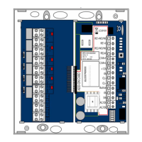
Configuration
Rotary switch
S1
Set release time
11 to 176 seconds (11-second grid)
during tempo-
rary release
In the case of a temporary release, the door is unlocked for the
time set on the rotary switch S1. The closed door is then locked
again as it closes. If the door is not closed, the pre-alarm is
triggered first and then the alarm.
during perma-
nent release via
terminals 9/10
(Fig. 4)
In the case of permanent release, the door is unlocked for the
duration of actuation. The door is then locked again as it
closes. If the door is not closed, the pre-alarm is triggered first
and then the alarm.
The behaviour of the temporary and permanent release also depends on the
settings via JP1 (Tab. 1) and DIP switch S4– 1 Tab. 2.
Rotary switch S2
in mode 1
Set pre-alarm duration
4 to 64 seconds (4-second grid)
Pre-alarm A pre-alarm remains activated when the door is open for the
time set on rotary switch S2. Then an alarm is triggered (Tab. 2
– DIP switch S4 – 1)
Rotary switch S2
in mode 2
Set participant address
Bus address The participant address is set on rotary switch S3 (“Configura-
tion”, page46). The desired pre-alarm duration is set on
the DCB controller
Rotary switch S3
in mode 1
Set alarm duration
11 to 176 seconds (11-second grid)
Alarm An acoustic alarm remains active for the time set on rotary switch
S3. The acoustic alarm is then switched off. Until the alarm
is acknowledged, the relay contact on terminals 15/16 remains
closedand the visual alarm on terminal 21 (Fig. 4) remains active.
Rotary switch S3
in mode 2
Set participant address
Bus address The participant address is set on rotary switch S3 (“Configura-
tion”, page46). The desired alarm duration is set on the
DCB controller.
Tab. 3
Rotary switch S1
(Fig. 5)
Tab. 4
Rotary switch S2
(Fig. 5)
Tab. 5
Rotary switch S3
(Fig. 5)
 Loading...