51
ENEN
Configuration
Mode 2– bus operation
The operating mode is set via DIP switch P4-5 (Tab. 2).
Even if the escape door control terminal is operated in mode 2 on the DC bus in
conjunction with a DCB controller 970-TSBC, the escape door is controlled and
monitored via the control terminal.
The entire range of functions already described for the control terminal and the
sequence of the individual functions are also available in bus operation.
Some functions, for example pre-alarm duration and duration of an acoustic
alarm, can be set via the DCB controller 970-TSBC (separate manual D01165).
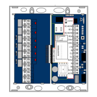
Bus connection
A DCB controller 970-TSBC is connected to the terminals Data and GND (Fig. 4
page46) via a two-wire bus line.
Important!
Risk of destruction and malfunction in the event of faulty connection:The bus
line must be carefully connected with the correct polarity for all components.
Incorrect connection can destroy the devices and block the entire data bus.
· Before commissioning, carefully check all connections for correct polarity.
Setting the bus address
Each component in the door control bus (data bus) must be assigned a unique
address.
The address range is set on rotary switch S3, the address in the address range on
rotary switch S2. This corresponds to a numbering in the hexadecimal system.
only with
model 1338-20
A
 Loading...