18
CHANGING THE DIRECTION OF THE SOLENOID ACTION FAIL LOCKED -> FAIL
UNLOCKED
Fig. A
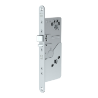
When the arrows on the changer and on the lock case are positioned
as shown in figure B, the lock is set on fail locked mode:
- power on -> the controlled handle will open the lock
- power off -> the controlled handle will not open the lock
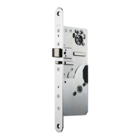
When the arrows on the changer and on the lock case are positioned
as shown in figure C, the lock is set on fail unlocked mode:
- power on -> the controlled handle will not open the lock
- power off ->, the controlled handle will open the lock
CHANGING THE OPENING DIRECTION OF THE TRIGGER BOLT
1. Loosen the fixing screw of the trigger bolt.
2. Pull the trigger bolt out and turn it round.
3. Put the trigger bolt back to place.
4. Tighten the fixing screw.
CHANGING THE OPENING DIRECTION OF THE LATCH BOLT
5. Push the bolt in.
6. Unscrew the fixing screw of the bolt head.
7. Pull the bolt head out and turn it round.
Fastening the bolt at 14 mm position:
1. Put the bolt head in place and push it in the lock case.
2. Insert the fixing screw to the opposite side of where it was before
and tighten it.
Fastening the bolt at 20 mm position:
1. Put the bolt head in place and push it in the lock case.
2. Press the handle to open the lock case mechanism. The body of the bolt
is withdrawn completely to the back and the outer of the two holes in the body
will be located at the hole of the bolt heads fixing screw.
3. Insert the fixing screw to the opposite side of where it was before and tighten
it. Check the function of the bolt.
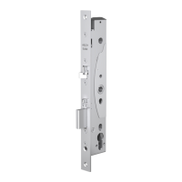
1. Unscrew the fixing screw and pull out the changer.
2. Turn the changer round as shown in the figure A.
3. Put the changer back and screw in the fixing screw. Make sure the changer is
straight and fits tightly in the lock case.
Fig. B
Fig. C
Fig. D
Fig. D
Fig. E
Fig. F
ENGLISH

 Loading...