Norton® is a registered trademark of Yale Security Inc., an ASSA ABLOY Group company.
Copyright © 2010, 2013 Yale Security Inc., an ASSA ABLOY Group company. All rights reserved.
Reproduction in whole or in part without the express written permission of Yale Security Inc. is prohibited.
ASSA ABLOY
80-9357-0001-020 (09-13)
2A. Installation Sequence Continued
Step 5: Install main arm onto pinion shaft of unit at a 90° angle to the
door frame. Align arm mark “S” with the flat corner of the
pinion shaft square. (See Fig. 3 below.)
Step 6: Secure main arm to pinion with 1/4-20 Flange Head Screw
provided. Tighten screw with 7/16" wrench or socket.
Step 7: Mount arm shoe to door using 2 1/4-20 screws & sex nuts
provided with screw pack.
Step 8: PRELOAD ARM (See Fig. 4, below): Remove 1/4-20 hex
head screw on adjusting rod and insert adjusting rod into
arm slide. Reinstall 1/4-20 screw and leave loose. Rotate
main arm in direction away from the hinge edge until the
adjusting rod and arm slide are perpendicular (at a 90°
angle) to the door frame. Tighten the 1/4-20 hex head screw
on the adjusting rod to secure arm in this new position.
Step 9: Adjust closing power of unit (See Fig. 5) - Using a 1/8” allen
wrench, turn the power adjustment shaft clockwise to
increase door closing power. Door control is shipped set at
midpoint of power setting. Maximum closing power can be
achieved with 8 (360°) clockwise turns of the power
adjustment screw.
Step 10: Adjust Hydraulic valves using a 1/8” hex wrench to obtain
proper door closing speeds. See following illustrations. Refer
to Table 1 on page 5 for recommended minimum opening /
closing times per ANSI/BHMA A156.19.
Closing Cycle – Make adjustments, as necessary, to the
Sweep Speed "S" valve and Latch Speed "L" valve. See
Fig. 6 below for location of valves. Turn valves clockwise to
reduce speed, counter clockwise to increase speed.
Opening Cycle – Adjust Backcheck, "B" valve, as
necessary, for hydraulic resistance to door opening in the
backcheck range. See illustration at bottom of this page for
location of valve.
NOTE: Too much Backcheck, "B" valve, can affect the
operation of the units pump, preventing units from fully
opening the door. This valve may require fine tuning
after all other adjustments have been made.
Note: A.D.A. requires that from an open position of 70°,
the door will take at least 3 seconds to move to a point
3” (75mm) from the latched position, measured at the
leading edge of the door.
Step 11: Make wiring connections using Wiring Instructions on Page
below and on Page 8.
R
L
Y
S
Z
Arm Mark
Pinion Flat
Figure 3
Figure 4
Adjusting
Rod
Arm
Slide
Door
Shoe
Main
Arm
Power
Adjustment
1/8"
Hex
Key
Increase
Power
Decrease
Power
Figure 5
1/8"
Hex
Key
Slower
Closing
Faster
Closing
Closing Cycle
Closed
10°
e
g
n
a
R
h
c
t
a
L
e
g
n
a
R
p
e
e
w
S
1/8"
Hex
Key
Increase
Cushion
Decrease
Cushion
Opening Cycle
B
a
c
k
c
h
e
c
k
g
n
i
n
e
p
O
Sweep Valve
Latch Valve
Backcheck
Valve
Figure 6
3. Electrical Connections and Final Setup
Step 1: Confirm all mechanical adjustments have been made and
wiring connected per Page 8.
Step 2: Turn on facility’s main circuit breaker.
Step 3: Turn power to unit on at the Unit Power Switch and turn the
Breaker Switch to “RESET”.
Step 4: Using a short jumper cable, jump terminals 1 and 2, see Fig.
2 below, to activate unit. When door reaches 20°, switch
Breaker Switch to “OFF” position cutting power to the unit.
Allow door to fully close (door may be manually pulled
closed).
(Continue to next page.)
Breaker
Switch
Unit Power Switch
1
2
3
4
1
2
3
4
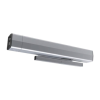
Figure 2
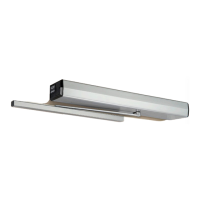
Figure 1
Page 7
 Loading...