Copyright © 2017 Yale Security Inc., an ASSA ABLOY Group company. All rights reserved.
Reproduction in whole or in part without the express written permission of Yale Security Inc. is prohibited.
80-9360-1020-020 Rev 1 02/17
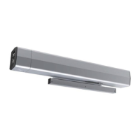
Disassemble Closer Sub-Assembly
3c
A. Disconnect wiring harnesses from Closer Sub-Assembly to Back Plate Assembly.
B. Loosen 4 screws holding the Closer Sub-Assembly.
C. Slide Closer Sub-Assembly to side and slide key hole in back plate over screws to
remove Sub-Assembly.
From Closer
Sub-Assembly
From Back
Plate Assembly
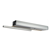
Assemble Closer Sub-Assembly
3d
A. i) Install new Closer Sub-Assembly over screws in Step 3c with closer spring tube
under power supply and ii) slide Closer Sub-Assembly toward Hinge edge of door.
NOTE: Valves on door closer should be facing away from chain.
B. Secure screws for Closer Sub-Assembly from Step 3c.
C. Secure top of Sub-Assembly to Blocking (for masonry, use anchors and spacers).
D. Connect wiring harnesses from Closer Sub-Assembly to Back Plate Assembly.
Connectors are keyed and only connect in one direction. Connectors will lock.
i
ii
i
ii
From Closer
Sub-Assembly
From Back
Plate Assembly
Page 5
Assemble Arm to Pinion
3e
A. i)Slide Adjusting Rod into Tube of Arm Slide and Tube
Assembly. ii) Place square of Main Arm onto pinion
with pinion flat and arm marking as shown below.
i
ii
Adjusting
Rod
Main Arm
Arm Slide Tube
Pinion Flat
Arm Marking

 Loading...