Copyright © 2020, Sargent Manufacturing Company, an ASSA ABLOY Group company. All rights reserved.
Reproductions in whole or in part without express written permission of Sargent Manufacturing Company is prohibited.
05/31/20
A8239B • 800-810-WIRE (9473) • www.sargentlock.com14
SE LP10 7000 Series Multi Point Lock
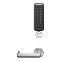
1. Fit trim bezel around the reader. Ensure access hole in the bezel aligns with screw hole on
reader. The reader should be mounted so the holes face the bottom of door (Fig. 5B).
2. Align top of reader with top of backplate. Pivot reader down until seated.
Guide wires as needed to avoid pinching.
3. Secure the reader with (1) #6-32 x 3/8” Phillips or anti-tamper security torx screw to the
mounting plate (Fig. 5C).
5 Installation of SE LP10 Reader & Trim Bezel
Fig. 5A
Observe precautions for handling electrostatic sensitive devices.
!
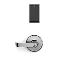
Reader
Module
If the SE LP10 reader is installed with a module (Fig. 5A), make sure that
the reader is powered down when inserting/removing the module; i.e.,
do not “hot-plug” (remove/insert while reader is powered) module as it
may damage the reader.
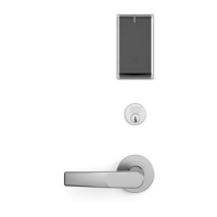
Fig. 6C
Trim Bezel
Reader
Outside of
Door
Detail
Torx
security
screw
Fig. 6B
 Loading...