Copyright © 2020, Sargent Manufacturing Company, an ASSA ABLOY Group company. All rights reserved.
Reproductions in whole or in part without express written permission of Sargent Manufacturing Company is prohibited.
05/31/20
A8239B • 800-810-WIRE (9473) • www.sargentlock.com6
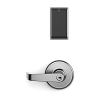
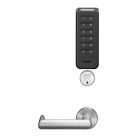
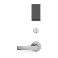
SE LP10 7000 Series Multi Point Lock
Wiring Diagrams
5
Product 8 PIN CONNECTOR 4 PIN CONNECTOR
1-Black 2-Red 3-White 4-Green 5-Orange 6-Blue 7-Brown 8-Yellow 1-Violet 2-Gray 3-Pink 4-Tan
ACCESS CONTROL DEVICES: SE LP10 7000 MP Lock, ElectroLynx wire Color / Function assignments
12VDC
(Reader)
WIEGAND WIEGAND RX RX EGND TAMPER 12/24 VDC
(LOCK RELAY)
DPS DPS
GREEN_LED*
SARGENT -
SE LP10
7000 MP
NEG POS DATA_1 DATA_0 NO COM EGND OPEN
COLLECTOR
NEG POS NC COM
INPUT
Default Operation Mode:
• Red LED ‘ON’ when powered.
• Presenting a 13.56MHz or 125 kHz credential causes LED to briefly turn green and then return to
red state.
• Presenting a FIPS 201 PIV credential causes LED to turn amber as credential is authenticated.
Reader emits a short beep when credential is successfully read. Reference Diagram #1.
PIN 4 (Tan –DPS COM )
PIN 2 (Gray – Lock POS)
PIN 1 (Violet – Lock NEG)
PIN 3 (Pink – DPS NC)
Note: NC= Normally Closed
NO= Normally Open
PIN 8 (Yellow – TAMPER)
PIN 6 (Blue – RX COM)
PIN 4 (Green – Data 0)
PIN 2 (Red – Reader POS)
PIN 1 (Black – Reader NEG)
PIN 3 (White – Data 1)
PIN 5 (Orange – RX NO)
PIN 7 (Brown - EGND)
PIN 8 (Yellow – Green LED)
PIN 6 (Blue – RX COM)
PIN 4 (Green – Data 0)
PIN 2 (Red – Reader POS)
PIN 1 (Black – Reader NEG)
PIN 3 (White – Data 1)
PIN 5 (Orange – RX NO)
PIN 7 (Brown - EGND)
Optional Alternate Indicator Mode:
*Diagrams on following pages
Optional TAMPER Operation Mode:
• Connect Yellow TAMPER wire from ElectroLynx cable to desired EAC panel control line.
Reference Diagram #1.
• As appropriate, use the configuration card to activate desired mode on reader.
• Connect GREEN_LED input to switch controlled by panel. Shorting GREEN_LED to READER_NEG
(Black) with panel switch will override reader LED to keep it green.
PIN 4 (Tan –DPS COM )
PIN 2 (Gray – Lock POS)
PIN 1 (Violet – Lock NEG)
PIN 3 (Pink – DPS NC)
 Loading...