1-800-810-WIRE • www.sargentlock.com • A8205B 14
Copyright © 2018, Sargent Manufacturing Company, an ASSA ABLOY Group company. All rights reserved.
Reproductions in whole or in part without express written permission of Sargent Manufacturing Company is prohibited.
01/31/18
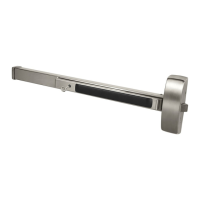
IN220 Exit Device
NOTE: Exit chassis harness consists of a 6-pin female connector and two
different-sized ground lugs (Fig. 3A)
1. Feed 6-pin connector and larger ground lug straight through to outside of
door (Fig. 3A, B) while feeding smaller ground lug into wire hole, up through
wire channel and out through inside of door (Fig. 3C).
DO NOT PINCH THE WIRE HARNESS.
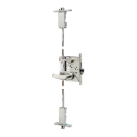
2. Begin to secure the exit chassis with through bolts
to the ET trim using (2) 1/4 -20 x 2-3/8”
flat head machine screws.
Inside of Door
(2) 1/4 x 2-3/8”
Flathead Machine
Screws (secures ET)
Exit Chassis
3 Mount Exit Device Chassis
Fig. 3A
Fig. 3B
Outside of
Door
Inside of Door
Fig. 3C
 Loading...