01/31/18
33 1-800-810-WIRE • www.sargentlock.com • A8205B
Copyright © 2018, Sargent Manufacturing Company, an ASSA ABLOY Group company. All rights reserved.
Reproductions in whole or in part without express written permission of Sargent Manufacturing Company is prohibited.
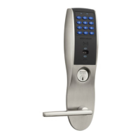
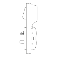
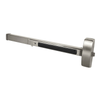
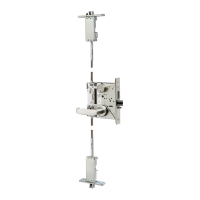
IN220 Exit Device
10
Installation of Inside Component Assembly
1. Insert top tabs of controller into slots on mounting plate (Fig. 10A, B).
2. Ensure proper alignment of board-to-board connectors while pivoting bottom of controller
toward door until tab on bottom snaps securely into place on mounting plate.
CAUTION: To avoid possible damage to board-to-board connectors,
care should be taken when securing controller to mounting
plate. If there is resistance when securing, detach controller
to determine cause before re-attaching controller.
Fig. 10B
4. Remove pull tab from its position
beneath the coin cell by pulling
on tab in direction of arrows
printed on tab (Fig. 10B).
3. Connect RJ45 male connector to female RJ45 port on controller board (Fig. 10B).
Fig. 10A
Coin Cell
Pull Tab
 Loading...