V9.7 01/05/20 UD0011 Page 160 of 177
This Document is uncontrolled when printed unless over stamped “CONTROLLED DOCUMENT"
Additional Information
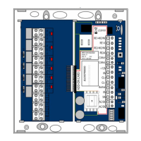
LED’s - There are two LEDs used to show status signals from the iMX28. Currently LED 2 is assigned to flash when the
internal memory is being accessed. LED 1 is not currently used but available for future debug use.
Relays Contact Specification - 2A 24V DC MAX (Resistive Load).
Relay & Battery Fuses - If the relays or battery are wired into the control PCB incorrectly there are spare fuses that
can handle an input for up to 15V.
Reader Connections – Below is a closer look at the reader connections.
The Reader 1 Connector supports Wiegand and Clock & Data card readers and shares the same pin-out as the original
Traka Touch and 16-bit board. The reader 12V connection is limited to 12V but if running from battery back-up it will
track the battery voltage down to approximately 10V.
 Loading...