September 2003
INSTALLATION INSTRUCTIONS
Page 21
5300LN Series Parts & Service Manual
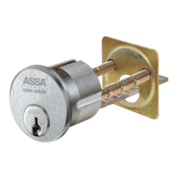
Insert lock body into door from
outside making sure that lock
body frame hooks latch case
and retractor engages bolt
tail(s).
(If lock body
does not engage latch easily,
check door preparation for
errors.)
DO NOT FORCE.
6. Install lock.
7.
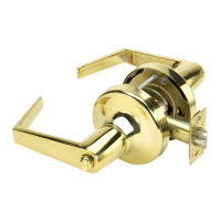
Install inside components
A. Slide inside rose support assembly onto lock body and tighten through bolts.
C. handle.Install lever For double cylinder functions, install the inside cylinder
and lever as shown on the next page.
B. Place rose scalp on rose support assembly, aligning the dimple with the
notch. Rotate the rose scalp clockwise to lock. Note: Repeat on outside rose
if necessary.
A.
B.
C.
D.
Remove lever and rose assembly (as one unit)
from lock body by removing two (2) screws.
Disengage rose plate from lock body and reinstall
per illustration below.
Assemble lever and rose assembly to the lock
body and secure with screws.
Adjust button as required (5302, 5303, 5307, and
5322 locks only). Depress retainer and adjust as
shown below
.
5. Adjust lock for door thickness.
If necessary
(Lock is packed preadjusted for 1-3/4"(44mm) doors.)
Latch
Retractor
engages bolt
tail(s)
Lockbody
Frame engages
latchcase
Through Bolt
Inside Rose
Support Assembly
Rose Scalp
Inside Lever
Tur n bu
tton
1st
1 3/8” Door
(35mm)
2nd
1 3/4” Door
(44mm)
3rd
2” & 2 1/4”
Door
(51mm & 57mm)
Position for thick doors
STD lock : 1-3/4” door
OPT lock : 2-1/4” door
Position for thin doors
STD lock : 1-3/8” door
OPT lock : 2”
door
Slide plate to disengage
Retainer Position
Outside Rose Plate Adjustment
 Loading...