For technical support contact Yale
®
at 800.438.1951 or support@yalelocks.com
An ASSA ABLOY Group brand
4
80-9470-0162-000 10/18
Delayed Egress
Installation Instructions
Exit Device
Copyright © 2018, ASSA ABLOY Access and Egress Hardware Group, Inc.
All rights reserved. Reproduction in whole or in part without the express written
permission of ASSA ABLOY Access and Egress Hardware Group, Inc. is prohibited.
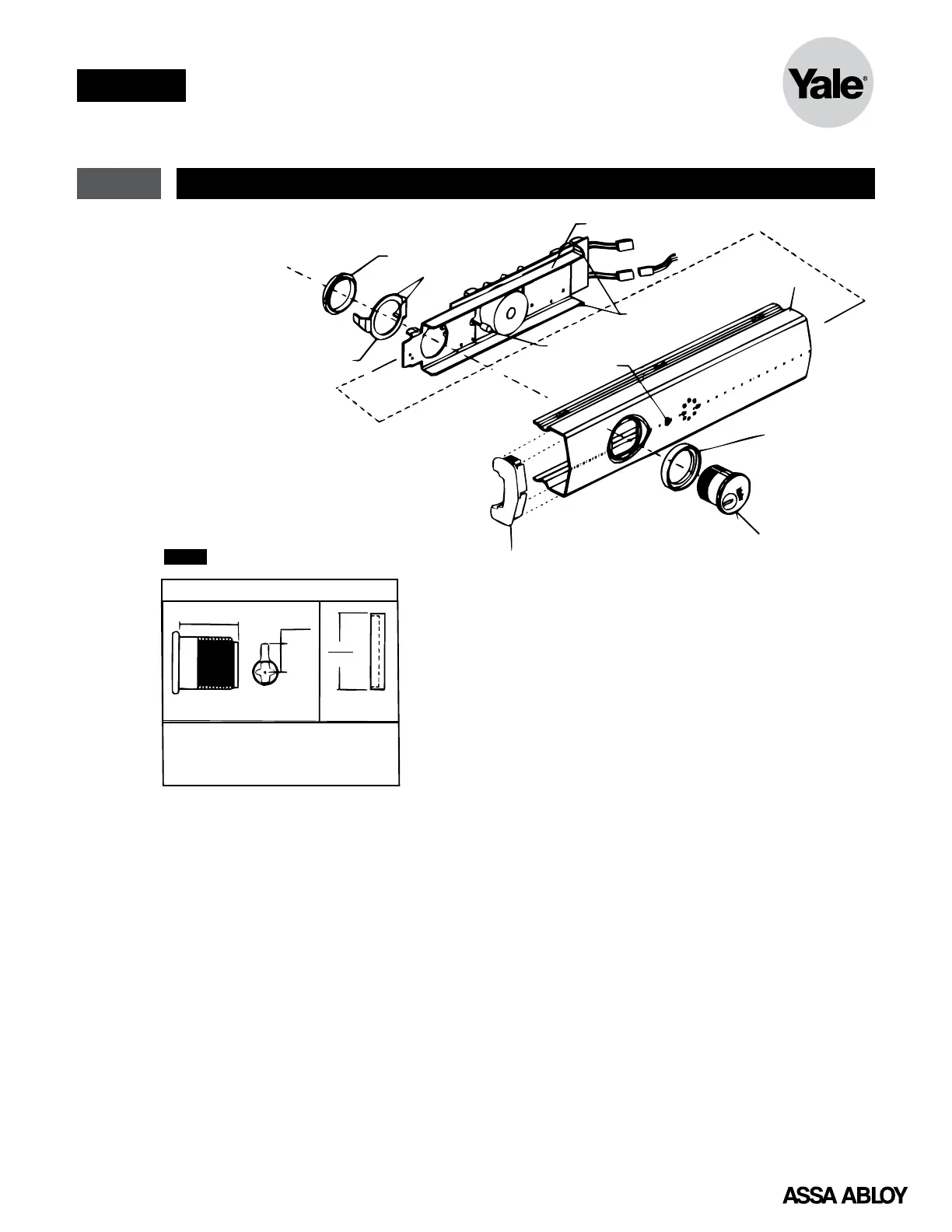
2 End Cover and P.C. Board Assembly
1. Trim device to proper length as required.
36" Exit Device - 1" maximum can be
trimmed
48" Exit Device - 6" maximum can be
trimmed
2. Carefully slide circuit board assembly into end
Cover to ensure indicator light (LED) is not
bent.
3. Insert mortise cylinder into end cover with
keyway horizontal, as shown.
4. Slide arming switch activator over mortise
cylinder so activator legs are on each side of
switch.
Figure 2
5. Insert flange of cylinder nut into arming
switch activator to allow rotation of
activator.
6. Tighten cylinder nut on mortise cylinder and
to secure circuit board assembly.
7. Verify assembly by rotating key counter
clockwise and clockwise. Key should move
freely and arming switch should trip for
both rotation directions. If key does not
rotate freely, verify cylinder nut was placed
in correct orientation. If arming switch does
not trip, activator legs on arming switch
activator can be bent to reduce or increase
rotational travel.
Rear Cover End Cap
1-1/8" (29)
Mortise Cylinder
with Ya le 2160 Ca
®
(Order Separately)
1765 Series
Cylinder Collar
(Order separately
when required)
End Cover
Circuit Board Assembly
Indicator Light ()LED
Lens Cover
Arming Switch Activator
Tabs
NOTE: Factory keyed orders will
be shipped assembled.
Cylinder Nut
Activator Legs
1765 Series
Cylinder Collar
1-1/8"
(29)
1-1/2"
(38)
2160 Cam
Dia
.742"
(18.9
mm)
Order Separately
®
NOTE: • Use Ya le
®
2153 x 2160 cam,
1-1/8" mortise cylinder
• For cylinders over 1-1/8",
use Yale
®
1765 Series cylinder ring.
Typical Mortise Cylinder
 Loading...