For technical support contact Yale
®
at 800.438.1951 or support@yalelocks.com
An ASSA ABLOY Group brand
5
80-9470-0162-000 10/18
Delayed Egress
Exit Device
Installation Instructions
Copyright © 2018, ASSA ABLOY Access and Egress Hardware Group, Inc.
All rights reserved. Reproduction in whole or in part without the express written
permission of ASSA ABLOY Access and Egress Hardware Group, Inc. is prohibited.
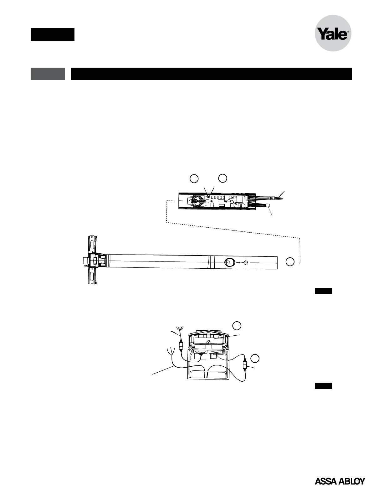
3 Installation of End Cover Assembly to Device
1. (J5) Nuisance Delay (Figure 3)
Jumper on - 3 seconds (Default)
Jumper off - immediate alarm
2. (J8) Reset Delay (Figure 3)
Jumper on - 10 seconds (Default)
Jumper off - 20 seconds
3. Slide end cover assembly into exit device.
(Figure 3) Do NOT pinch or crimp wires!
Figure 3
4. Connect device lock assembly to Connector
J1. (Figure 4)
5. Place wire connectors and excess wire
between end cover and circuit board.
(Figure 4) Check all connections before
proceeding.
J5 J8
Connector J2
To Power Transfer Hinge
Connector J1
Plugs into Device Lock Assembly
End Cover Assembly
Optional Wires
To Power Transfer
Lock Assembly Harness
Exit Device
1
2
3
Connector J2
To PowerTransfer Hinge
e/Secure wire
er to wiring diagram
for wiring)
Place Connector
and ExcessWire
in this Area
J1 Connector
Plugs into Device Lock Assembly
4
Figure 4
 Loading...