For technical support contact Yale
®
at 800.438.1951 or support@yalelocks.com
An ASSA ABLOY Group brand
7
80-9470-0162-000 10/18
Delayed Egress
Exit Device
Installation Instructions
Copyright © 2018, ASSA ABLOY Access and Egress Hardware Group, Inc.
All rights reserved. Reproduction in whole or in part without the express written
permission of ASSA ABLOY Access and Egress Hardware Group, Inc. is prohibited.
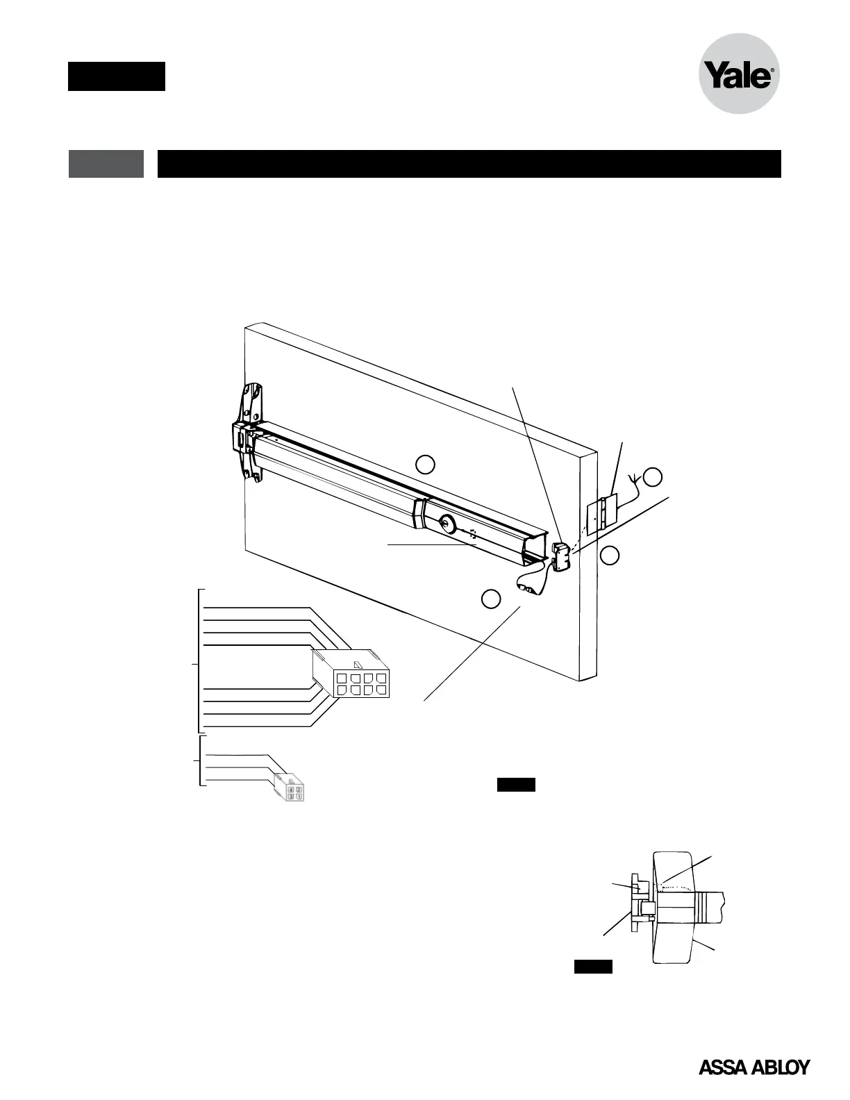
5 Device Mounting
Figure 5
1. For ElectroLynx Hinge Connector System:
Follow Section 4 wiring instructions.
2. For non-ElectroLynx door: Remove connector
at end of exit device and connect to incoming
wires from power source using wire nuts, butt
splices, etc.
NOTE:
• Switch contact rating: 5A @28VDC.
• Wire must be protected from abrasion.
• For use with Class II circuits only.
LHR Installation with O Monitor Shown
End Clamp
PowerTransfer
Hinge
Wire Access
3/4" Dia. hole on sam
centerline as device.
Inside face only.
End Cover
Installed
4()TA NNC
3()PNK NO
2(C)GRY
OMonitor
Connections
Pigtail harness
with 4-pin connector
Pigtail harness
with 8-pin connector
1
7
5
6
4
3
2
8
2(+)RED
8(Remote )YEL BYP
6(Secure )BLU NO
7(Remote)BRN RES
3(Alarm)WHT NC
5(Secure )ORG NC
1 (-)BLK
4(Alarm)GRN NO
Function
1
2
4
3
Figure 6
Security Package H Strike Magnet Installation
1. Mount strike to frame.
2. Line up magnet to strike.
3. Mark screw hole.
4. For security package, prep hole for one (1)
10-24 machine screw.
NOTE: LHR device magnet position shown. RHR
device will be located on bottom of strike.
Switch
Device
Strike
 Loading...