13
CONNECTIONS
OPERATING THE SC6540 WITH OMNIA II 8204 (Continued)
OPERATION
Once the SC6540 is incorporated into a test system, it will act as an extension of
the OMNIA II. The outputs will only activate while a test is being performed and
will deactivate when the test is not running. When a failure is detected, the test will
stop, the output will be deactivated and the OMNIA II will give a visual and audible
indication of failure. If steps were connected in sequence, the OMNIA II will indicate
a failure once it reaches the output that is connected to the defective device. The
SC6540 will not continue to test the other outputs until the RESET button is pressed,
the defective item is removed, and the TEST switch is pressed once again. The
SC6540 will then begin to test from the rst step in the program.
Secondary Scanner Power
Once the SC6540 Secondary is connected to the OMNIA II, the “power on”
LED will light as soon as the power switch of the OMNIA II is turned on.
Main Scanner Power
The SC6540 Main is powered on by flipping the switch on the rear panel of the
unit to the ON position.
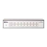
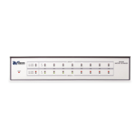
LED Indicators
The two leftmost LEDs for Module A and Module B indicate the type of module
that has been installed. If the Red LED is illuminated there is a High Voltage
module present. If the Green LED is illuminated there is a Ground Bond module
present. During a test, individual LED indicators for each output indicate
whether the output is set as High, Low, or Open. If the channel is set as a High
Voltage Output, Ground Bond Output, or Continuity Current Output the red
LED will light up. If the channel is set as Return, the green LED will light up. If
the High Voltage channel is set to Open, no LED will light up.
 Loading...