156
<Specifications for outputs of 11 to 16 bits>
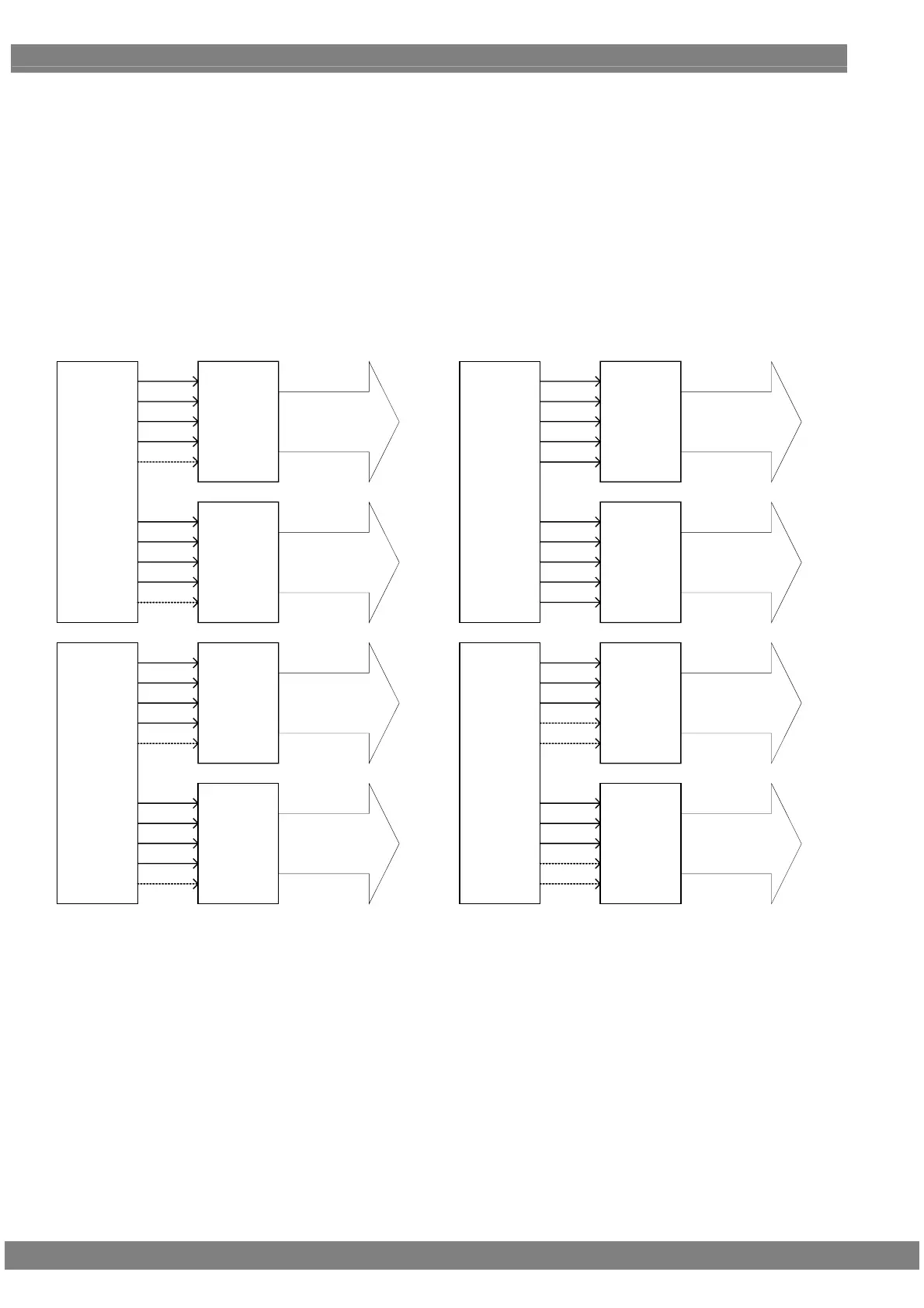
With outputs of 11 to 16 bits, 8 to 10 bits are treated as one output by the channel 1 and 2 set. The bits can be
allocated in two ways as shown below. However, when Single (Auto) or Dual (Auto) has been set as the LVDS
setting parameter mode, automatic switching is initiated to the channel 1 output for bits 8 to 10 and to the channel 2
output for bits 11 to 16.
When Single (10 bits), Dual (10 bits) or Quad (10 bits) has been set as the setting parameter mode, output is fixed
from channel 1.
When Single (16 bits) or Dual (16 bits) has been set as the setting parameter mode, output is fixed from channel 2.
*1: The signal lines indicated by the dotted lines in the above figure are not used.
*2: The specification for 8 + 8 bits output is the default setting.
RGB 8Bit
[7:0]
RGB 8Bit
[7:0]
RGB 8Bit
[15:8]
RGB 8Bit
[15:8]
TX1
TXOA
TXOB
TXOC
TXOD
TXOE
TXEA
TXEB
TXEC
TXED
TXEE
1CH
2CH
TX2
TXOA
TXOB
TXOC
TXOD
TXOE
TXEA
TXEB
TXEC
TXED
TXEE
3CH
4CH
RGB 6Bit
[5:0]
RGB 6Bit
[5:0]
RGB 10Bit
[15:6]
RGB 10Bit
[15:6]
TX1
TXOA
TXOB
TXOC
TXOD
TXOE
TXEA
TXEB
TXEC
TXED
TXEE
1CH
2CH
TX2
TXOA
TXOB
TXOC
TXOD
TXOE
TXEA
TXEB
TXEC
TXED
TXEE
3CH
4CH
【8 + 8 Bit 出力】 【10 + 6Bit 出力】
[8 + 8 bits output] [10 + 6 bits output]
 Loading...