Chapter 4 INTERFACE SETTINGS
157
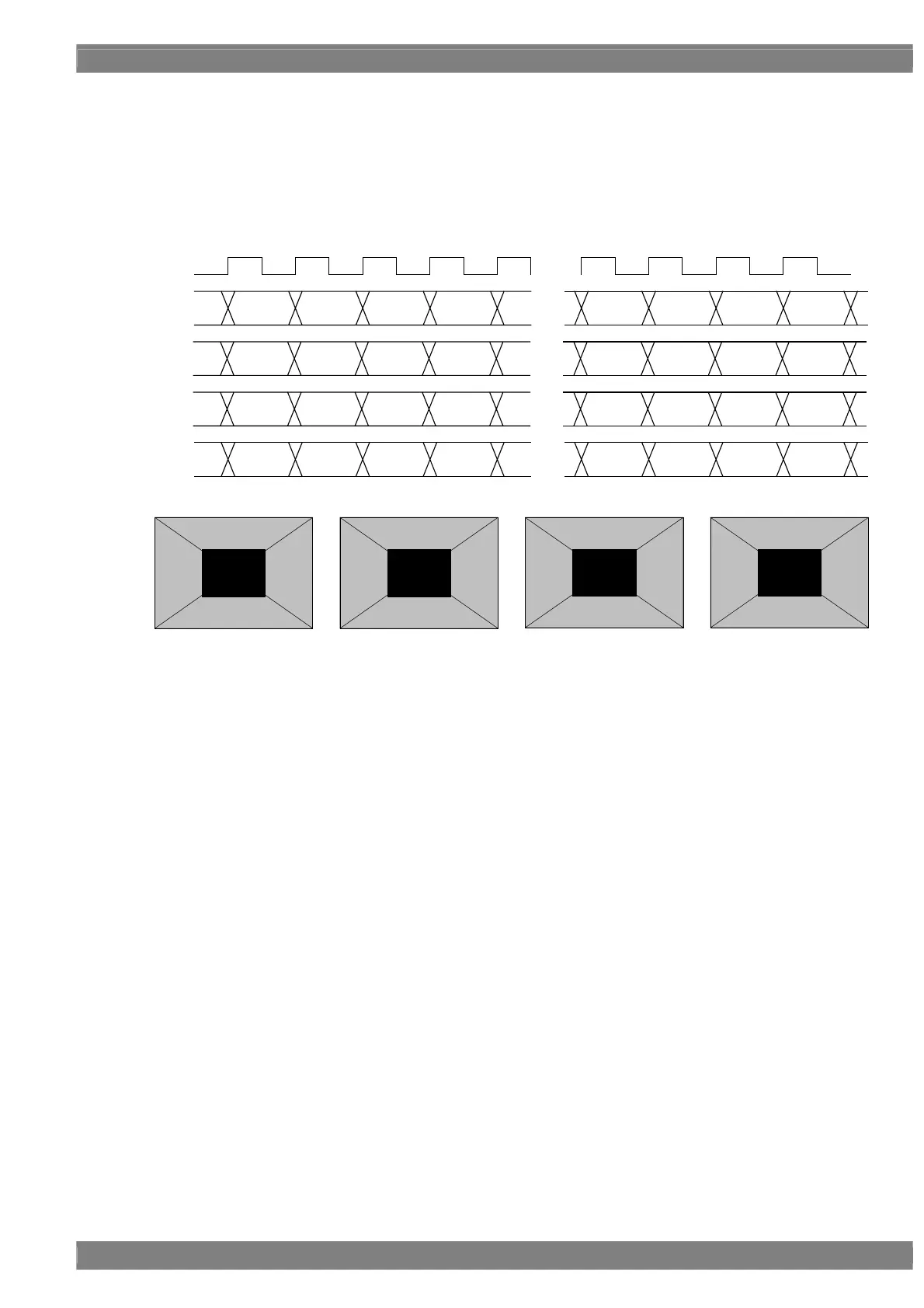
Setting (1) [Single (16 bits)], [Normal], configuration [10 + 6 bits]
The 16-bit images are output with channels 1 and 3 forming one set and channels 2 and 4 forming another set.
The 10 upper bits are output to channels 1 and 2, and the 6 lower bits are output to channels 3 and 4.
The example given here describes a case where the resolution is 1280 × 1024, the dot clock frequency is 108 MHz
with 16 bits level, 10 bits are output to channel 1 and 6 bits are output to channel 2.
D 0
[15:6]
D 1 D 2 D 3
・・・
・・・
[15:6] [15:6] [15:6]
D 1276 D 1277 D 1278 D 1279
CLK
108MHz
D 0 D 1 D 2 D 3
・・・
D 1276 D 1277 D 1278 D 1279
1CH
2CH
3CH
4CH
[5:0] [5:0] [5:0] [5:0]
[15:6] [15:6] [15:6] [15:6]
[5:0] [5:0] [5:0] [5:0]
D 0
[5:0]
D 1 D 2 D 3
・・・
[5:0] [5:0] [5:0]
D 1276 D 1277 D 1278 D 1279
[5:0] [5:0] [5:0] [5:0]
D 0 D 1 D 2 D 3
・・・
D 1276 D 1277 D 1278 D 1279
[15:6] [15:6] [15:6] [15:6] [15:6] [15:6] [15:6] [15:6]
Upper Bit [15:6]
Lower Bit [5:0]
Upper Bit [15:6]
Lower Bit [5:0]
1CH 2CH 3CH 4CH
 Loading...