Chapter 4 INTERFACE SETTINGS
261
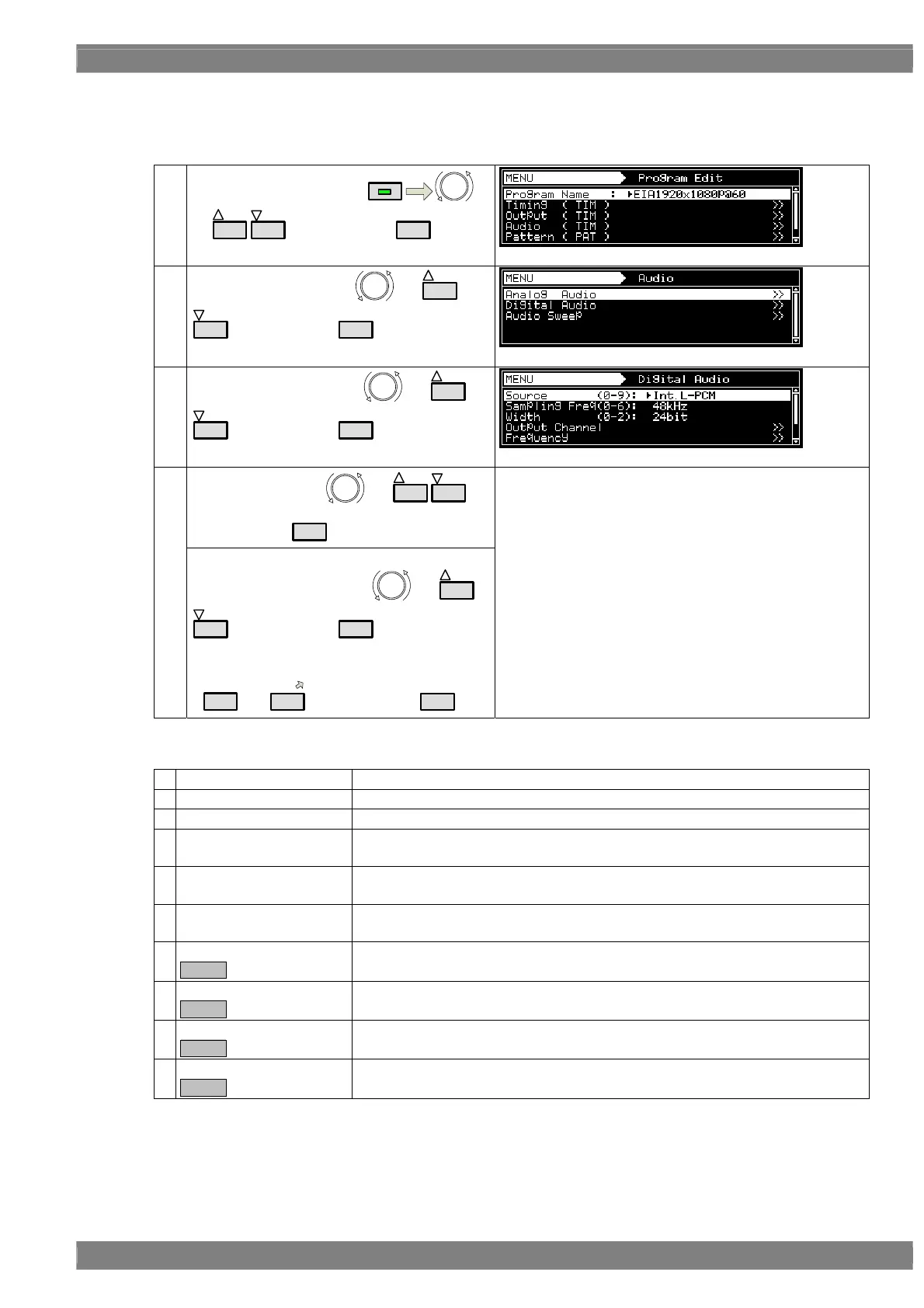
The operation procedure is described below.
Setting the sound source, frequency, level, etc.
(1)
Select Program Edit using
MENU
or
INC
DEC
, and then press
SET
.
(2)
Select Audio (TIM) using
or
INC
DEC
, and then press
SET
.
(3)
Select Digital Audio using
or
INC
DEC
, and then press
SET
.
Select Source using or
INC
DEC
,
and then press
SET
.
(4)
<Inputting the parameters>
Select the parameters using
or
INC
DEC
, and then press
SET
.
Alternatively:
Select the parameters using the number keys
(
0/STATUS
to
9/F
), and then press
SET
.
Select the sound source <Source>.
Depending on the selected sound source, the setting
parameters associated with that source will differ.
<Source>
0
OFF
No output.
1
Ext. Optical
The digital input (optical) is output. No parameters are provided. *
2
Ext. COAXIAL
The digital input (coaxial) is output. No parameters are provided. *
3
Ext. Analog to L-PCM
The analog input is converted to L-PCM, and output.
For further details, refer to <Ext. Analog to L-PCM setting parameters>.
4
Ext. Analog to DSD
The analog input is converted to DSD, and output.
For further details, refer to <Ext. Analog to DSD setting parameters>.
5
Int. L-PCM
Sine waves are output by the internal L-PCM.
For further details, refer to <Int. L-PCM setting parameters>.
Int. Non L-PCM
Option.
The sound of the non L-PCM stored in the internal memory is output.
For further details, refer to <Int. Non L-PCM setting parameters>.
Int.L-PCM(Flash)
Option.
The sound of the L-PCM stored in the internal memory is output.
For further details, refer to <Int.L-PCM (Flash) setting parameters>.
Int. DSD
Option.
The sound of the DSD stored in the internal memory is output.
For further details, refer to <Int. DSD setting parameters>.
Ext. I2S L-PCM
Option.
The non L-PCM input from the I2S connector is output.
For further details, refer to <Ext. I2S L-PCM setting parameters>.
 Loading...