Chapter 3 OPERATION
13
No. Item Description Display modes
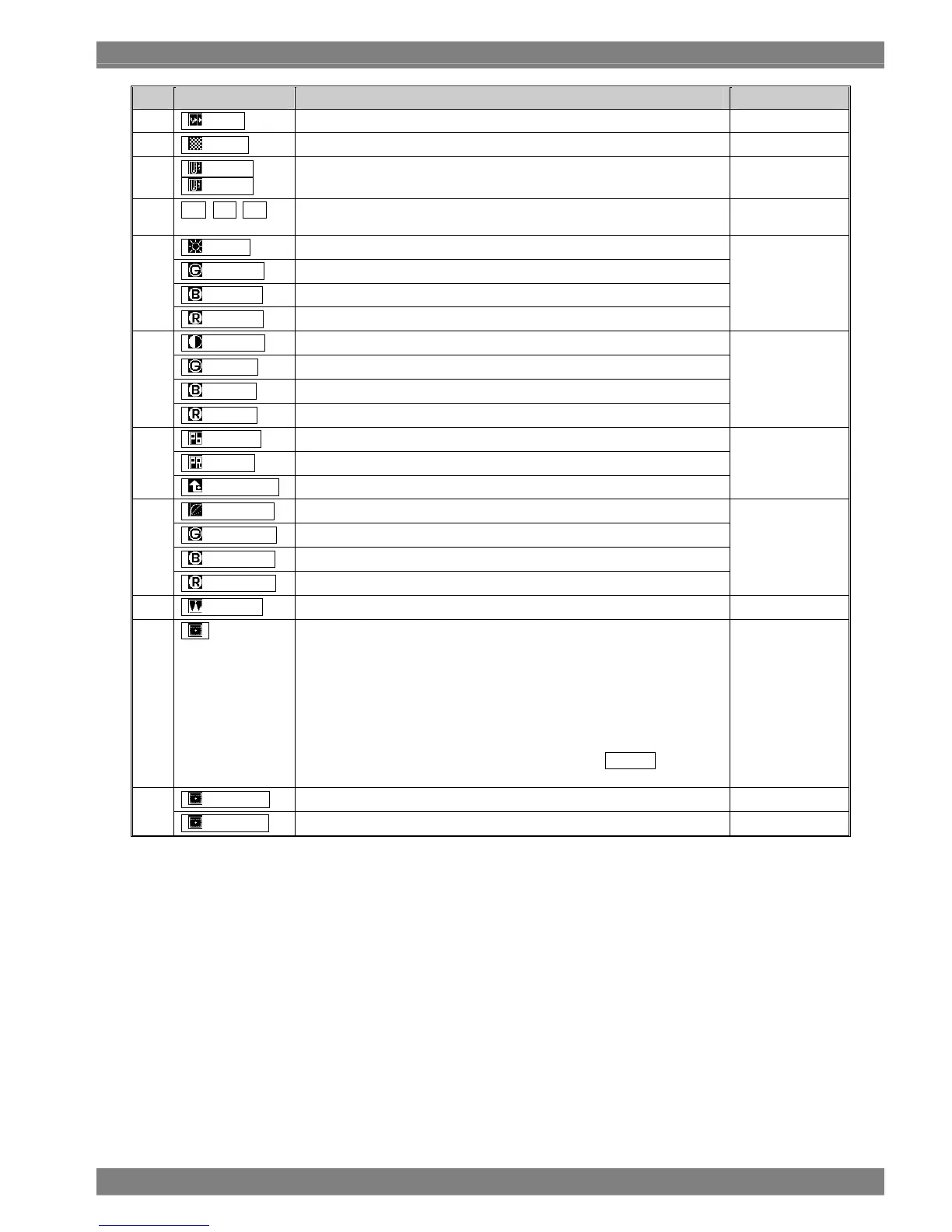
1
Filter
This indicates whether the filter is ON or OFF. P1, P2
2
Mono
This indicates whether monochrome is ON or OFF. P1, P2
3
6500K /
9300K
This indicates the color temperature of the liquid crystal which has been
set.
P1, P2
4
G B R
These indicate the ON or OFF status each for G, B and R. A highlighted
display denotes the ON status.
P1, P2
Bright
This indicates the brightness setting.
G-Bright
This indicates the G-brightness setting.
B-Bright
This indicates the B-brightness setting.
5
R-Bright
This indicates the R-brightness setting.
P1
Contrast
This indicates the contrast setting.
G-Cont
This indicates the G-contrast setting.
B-Cont
This indicates the B-contrast setting.
6
R-Cont
This indicates the R-contrast setting.
P1
Pb (Cb)
This indicates the Pb (Cb) setting.
Pr (Cr)
This indicates the Pr (Cr) setting.
7
ChromaUp
This multiplies the chroma signal by 3.
P1
Y-Gamma
This indicates the Y-gamma setting.
G-Gamma
This indicates the G-gamma setting.
B-Gamma
This indicates the B-gamma setting.
8
R-Gamma
This indicates the R-gamma setting.
P1
9
Peaking
This indicates the peaking setting. P1
10
(Marker)
Displayed here is a list of the usable markers. The currently selected
marker is highlighted.
<Types of markers>
FRAME, CENTER, USER, 95%, 93%, 88%, 80%, 4:3, 13:9, 14:9,
2.35:1, 1.85:1, 1.66:1
Note: When SD-SDI signals are input, the 4:3, 13:9 and 14:9 markers will
not be displayed even when one of these marker designations is
highlighted.
Furthermore, if there are no input signals and AUTO has been
selected for the format, the 1080 marker is displayed.
P1, P2
Marker H
This indicates the horizontal setting of the user marker. P2
11
Marker V
This indicates the vertical setting of the user marker. P2
Abbreviations used in display mode column:
P1
…
PICTURE1 mode, P2
…
PICTURE2 mode, P3
…
PICTURE3 mode, W
…
WAVEFORM mode, V
…
VECTOR mode, ML
…
MULTI mode,
ST
…
STATUS mode, A
…
AUDIO mode, PRE
…
PRESET mode, MN
…
MENU mode

 Loading...