EasyManua.ls Logo

AstroAI DM6000AR - User Manual

AstroAI DM6000AR
15 pages
Print Icon
To Next Page IconTo Next Page
Loading...
ASTROAI USER MANUAL
TRUE RMS DIGITAL MULTIMETER
Thank you for purchasing the True RMS 6000 Count Digital Multimeter from AstroAI. The
AstroAI True RMS Digital Multimeter is designed to be safely and accurately used by
professionals in a commercial setting or weekend DYer’s that need a little more utility from their
standard digital multimeter. This manual provides all safety information, operation instruction,
specifications, and maintenance for the meter. The instrument performs AC/DC Voltage, AC/DC
Current, Resistance, Audible Continuity, Diode, hFE, Frequency, Capacitance, and
Temperature Testing. Thank you again for choosing AstroAI, if you have any questions or
concerns regarding your product, please contact us at support@astroai.com.
NOTE: Fully read and understand this manual before using this Digital Multimeter.
WARNING: To avoid possible electric shock or personal injury, and to avoid possible damage to
the Meter or to the equipment being tested, adhere to the following rules:
Before using the Meter, inspect the exterior casing. Do not use the Meter if it is damaged
or if all or part of the exterior casing is removed. Look for cracks or missing plastic. Pay
special attention to the insulation around the connectors.
Inspect the test leads for damaged insulation or exposed metal. Check the test leads for
continuity.
Do not apply more than the rated voltage, as marked on the Meter, between the
terminals or between any terminal and grounding.
The manual rotary switch should be placed in the correct position before measurement
and should NOT be moved during measurement to prevent damage to the Meter.
When the Meter is working at an effective voltage over 60V in DC or 30V rms in AC,
special care should be taken because there is a danger of electric shock.
Use the proper terminals, function, and range for your measurements.
Do not use or store the Meter in a high-temperature environment, do not expose to high
levels of humidity, or near strong magnetic fields. The performance of the Meter may
deteriorate after dampening.
When using the test leads, keep your fingers behind the finger guards.
Disconnect circuit power and discharge all high-voltage capacitors before testing
resistance, continuity, diodes or hFE.
Replace the battery as soon as the battery indicator appears. With a low battery, the
Meter might produce false readings that can lead to electric shock and personal injury.
Remove the connection between the testing leads and the circuit being tested, and turn
the Meter power off before opening the Meter case.
When servicing the Meter, use only the same model number or identical electrical
specifications replacement parts.
The internal circuit of the Meter shall not be altered at will to avoid damage of the Meter
and any accident.
Question and Answer IconNeed help?

Do you have a question about the AstroAI DM6000AR and is the answer not in the manual?

AstroAI DM6000AR Specifications

General IconGeneral
True RMSYes
Auto-RangingYes
DC Voltage600mV/6V/60V/600V/1000V
AC Voltage600mV/6V/60V/600V/750V
DC Current600μA/6000μA/60mA/600mA/10A
AC Current600μA/6000μA/60mA/600mA/10A
Resistance600Ω/6kΩ/60kΩ/600kΩ/6MΩ/60MΩ
Duty Cycle0.1% - 99.9%
Diode TestYes
Continuity TestYes
Auto Power OffYes
Data HoldYes
Low Battery IndicatorYes
Display6000 counts, LCD
Temperature-40°C to 1000°C
Weight350g
Battery2 x AAA batteries
Safety RatingCAT III 600V
Capacitance10nF/100nF/1μF/10μF/100μF/1mF/10mF/100mF

Summary

General Safety Precautions

Safety Warnings and Guidelines

Adhere to rules to avoid electric shock, injury, or damage to meter/equipment.

Electrical Symbols and Specifications

Electrical Symbols Overview

Explains various symbols used on the multimeter and display.

General Specifications

Outlines display, sampling, size, selection, polarity, and overload indications.

Multimeter Diagram and Controls

Multimeter Component Diagram

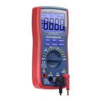
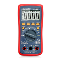
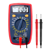
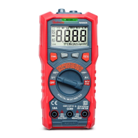
Identifies physical parts like screen, switch, terminals, and socket.

User Interface Controls

Describes function buttons like Select, Max/Min, Range, Relative, Hz/Duty.

Measurement Specifications

DC and AC Voltage Specifications

Details ranges, resolution, and accuracy for DC and AC voltage measurements.

Temperature and DC Current Specs

Covers temperature range, accuracy, and DC current ranges, resolution, and accuracy.

Transistor, AC Current, Resistance Specs

Details hFE, AC current, and resistance measurement specifications.

Diode, Continuity, Capacitance, Frequency

Summarizes specifications for diode, continuity, capacitance, and frequency tests.

Operating Instructions

Performing Voltage and Current Measurements

Guides on how to measure DC/AC voltage and current.

Performing Resistance and Continuity Tests

Instructions for resistance and continuity measurements.

Performing Diode, Transistor, Temperature Tests

Details on testing diodes, transistors, and temperature.

Performing Capacitance and Frequency Measurements

Guides for capacitance and frequency measurements.

Advanced Operations and Maintenance

Clamp Meter and Auto Power Off

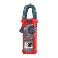
Instructions for clamp measurement and auto power off feature.

Battery and Fuse Replacement

Procedures for replacing the battery and fuses.

Product Information and Warranty

Included Accessories

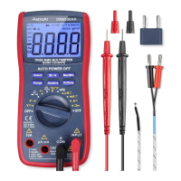
Lists items included in the box.

Disposal and Warranty Details

Information on product disposal and warranty terms.

Related product manuals