18 ASUS A7V-VM User’s Manual
Connectors
2. H/W SETUP
2. HARDWARE SETUP
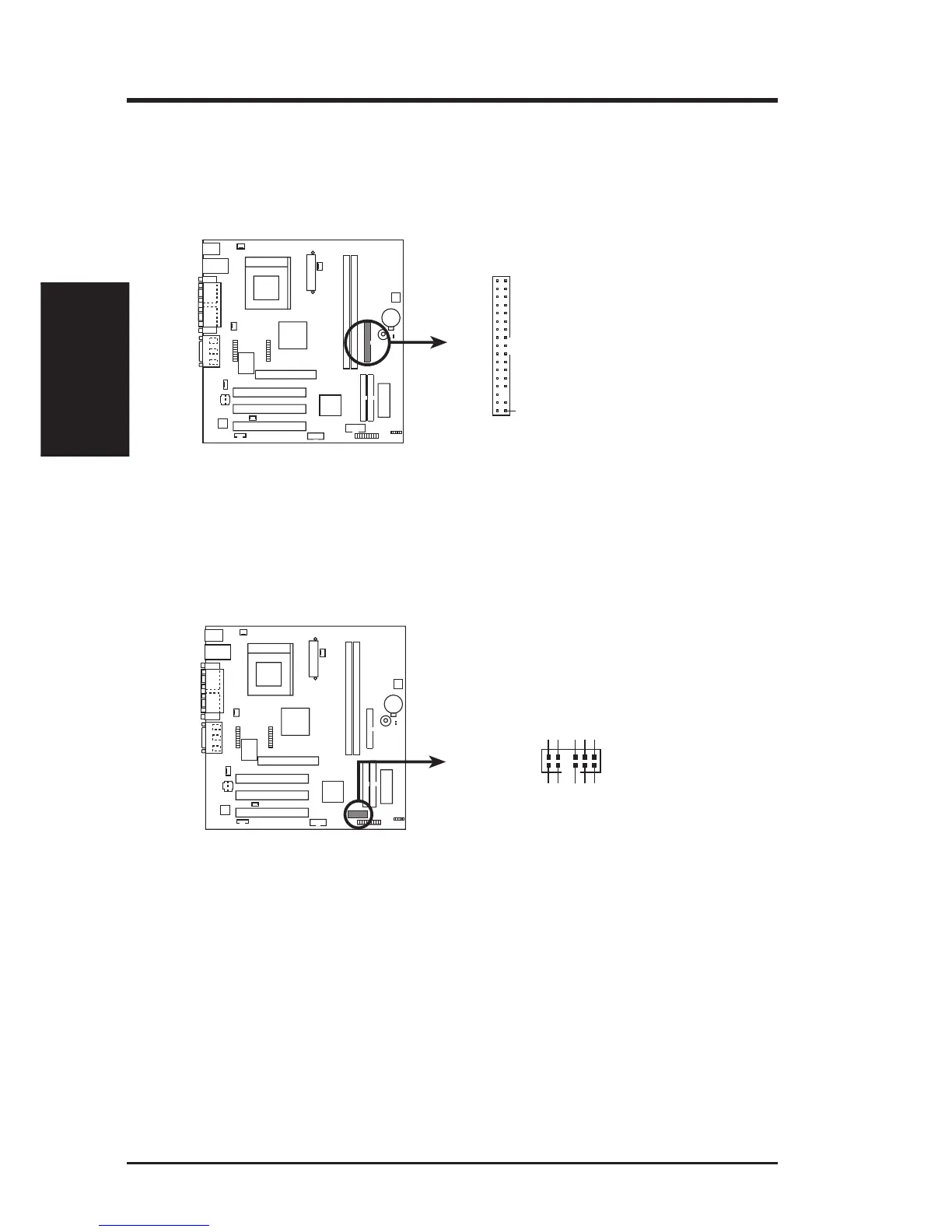
11) Floppy Disk Drive Connector (34-1pin FLOPPY)
This connector supports the provided floppy drive ribbon cable. After connect-
ing the single end to the board, connect the two plugs on the other end to the
floppy drives. (Pin 5 is removed to prevent inserting in the wrong orienta-
tion when using ribbon cables with pin 5 plugged).
NOTE: Orient the red markings on
the floppy ribbon cable to
PIN 1
A7V-VM Floppy Disk Drive Connector
PIN 1
A7V-VM
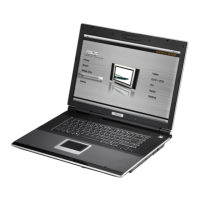
12) USB Header (12-2 pin HP_USB)
If the USB Ports on the back panels are inadequate, connect an optional USB
connector set to this header and mount it to an open slot on your chassis.
A7V-VM USB Port
1
2
11
12
GNDGND
GNDGND
USBP–USBP–
USBP+USBP+
USB PowerUSB Power
HP-USB
A7V-VM