20 ASUS A7V-VM User’s Manual
Connectors
2. H/W SETUP
2. HARDWARE SETUP
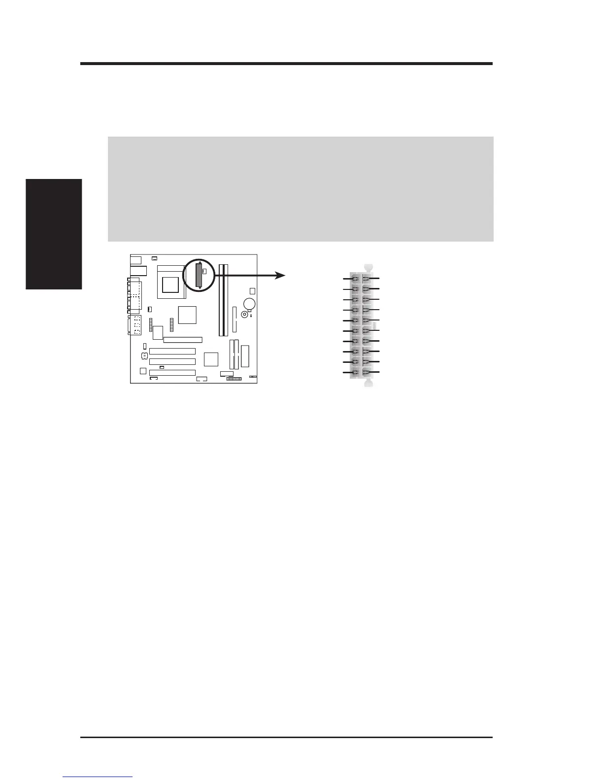
15) ATX Power Supply Connector (20-pin block ATXPWR)
This connector connects to an ATX power supply. The plug from the power sup-
ply will only insert in one orientation because of the different hole sizes. Find the
proper orientation and push down firmly making sure that the pins are aligned.
IMPORTANT: Make sure that your ATX power supply (minimum recommended
wattage: 200 watts; 235W for a fully-configured system) can supply at least 20
amperes on the +5-volt lead and at least 10mA (750mA recommended) on the +5-
volt standby lead (+5VSB). Your system may become unstable/unreliable and may
experience difficulty in powering up if your power supply is inadequate. For Wake-
On-LAN support, your ATX power supply must supply at least 750mA +5VSB.
A7V-VM
A7V-VM ATX Power Connector
+3.3 Volts
-12.0 Volts
Ground
Power Supply On
Ground
Ground
Ground
-5.0 Volts
+5.0 Volts
+5.0 Volts
Power Good
+12.0 Volts
+3.3 Volts
+3.3 Volts
Ground
+5.0 Volts
Ground
+5.0 Volts
Ground
+5V Standby
16) System Message LED Lead (2-pin MLED)
This indicates whether a message has been received from a fax/modem. The
LED will remain lit when there is no signal and blink when there is data re-
ceived. This function requires an ACPI OS and driver support.
17) System Management Interrupt Lead (2-pin SMI)
This allows the user to manually place the system into a suspend mode or “Green”
mode, where system activity is decreased to save electricity and expand the life
of certain components when the system is not in use. This 2-pin connector con-
nects to the case-mounted suspend switch.
18) System Warning Speaker Connector (4-pin SPK)
This 4-pin connector connects to the case-mounted speaker.
19) Reset Switch Lead (2-pin RESET)
This 2-pin connector connects to the case-mounted reset switch for rebooting
your computer without having to turn off your power switch. This is a preferred
method of rebooting to prolong the life of the system’s power supply.
20) System Power LED Lead (3-pin PLED)
This 3-pin connector connects the system power LED, which lights when the
system is powered on and blinks when it is in sleep mode.