Do you have a question about the Asus AeroActive Cooler 7 and is the answer not in the manual?
Illustrates the top side of the AeroActive Cooler 7 (AY2301), identifying key buttons and covers.
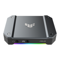
Details the front view of the AeroActive Cooler 7 (AY2301), showing buttons and lights.
Presents the rear view of the AeroActive Cooler 7 (AY2301), highlighting buttons and lighting features.
Shows the bottom view of the AeroActive Cooler 7 (AY2301), detailing kickstand and ports.
Depicts the side view of the AeroActive Cooler 7 (AY2301), focusing on cooling fins.
Highlights the Kapton tape application on the mainboard for insulation or protection.
Features the cooling fan component of the AeroActive Cooler 7 (AY2301).
Shows the heatsink assembly for the fandongle module.
Details the Key FPC L Kapton component, potentially for LED abnormalities.
Instructs on releasing and removing the top plastic cushion from the holder.
Details loosening screws and using a pick to remove the mid cover case.
Guides on removing polyimide tapes and unplugging various cables from the mainboard.
Explains using a pick to remove the mid thermal module from the front case.
Instructs on separating the front cover and fan thermal module from the mid thermal module.
The ASUS AeroActive Cooler 7 (AY2301) is a dedicated cooling accessory designed to enhance the performance and user experience of compatible devices, likely high-performance smartphones, by actively managing their thermal output. This service manual provides comprehensive guidelines for the disassembly, repair, and maintenance of the AY2301, ensuring optimal service and support for technicians.
The primary function of the AeroActive Cooler 7 is to provide active cooling to a connected device, preventing overheating during intensive tasks such as gaming, video editing, or prolonged usage. It achieves this through an integrated fan and a thermal module that dissipates heat away from the device. Beyond cooling, the AY2301 also expands the device's connectivity and ergonomic features. It includes a kickstand for hands-free viewing, a USB Type-C port for charging or data transfer, and a 3.5mm headphone jack, addressing common limitations of modern mobile devices. Additionally, it incorporates a subwoofer to enhance audio output, providing a more immersive experience. The cooler features various buttons for control, including a power button, cooler buttons, and an unlock button, allowing users to manage its functions directly. Aura lighting is also integrated, likely for aesthetic customization and to complement the gaming aesthetic of compatible ASUS ROG devices.
The AeroActive Cooler 7 is designed for ease of attachment and detachment, indicated by the presence of an unlock button. Once attached, it provides immediate thermal management, which is crucial for sustaining peak performance in demanding applications. The cooler buttons likely offer control over fan speed or cooling modes, allowing users to adjust the cooling intensity based on their needs. The integrated kickstand offers a convenient way to prop up the connected device, ideal for media consumption or gaming with external controllers. The additional USB Type-C port ensures that the device can be charged or connected to peripherals even while the cooler is in use, preventing the cooler from monopolizing the device's primary port. The 3.5mm headphone jack restores a widely appreciated audio output option, which is often absent in newer mobile devices, catering to users who prefer wired headphones. The subwoofer enhances the audio experience, providing richer bass and a more dynamic sound profile, particularly beneficial for gaming and multimedia. The Aura light feature allows for personalization, enabling users to match the cooler's lighting with their other ROG peripherals or personal preferences. The overall design emphasizes an ergonomic grip, making extended usage more comfortable by providing a more substantial and contoured surface to hold.
The service manual outlines detailed procedures for the disassembly and reassembly of the AeroActive Cooler 7, which are essential for maintenance and repair. Key components identified for service include various rubber parts (cooling rubber, key rubber, USB rubber) that likely serve as protective seals, anti-slip surfaces, or vibration dampeners. The presence of these rubber components suggests that they might be replaceable if they wear out or get damaged, which is a common maintenance task for accessories that experience frequent handling. The manual also details the internal components such as the fandongle base assembly, cooling chip, heatsink thermal pad, fan function board, fan gasket, and USB FPC (Flexible Printed Circuit) board. This level of detail indicates that individual components, such as the fan or specific circuit boards, can be replaced if they malfunction. The inclusion of conductive tapes and rings suggests that maintaining proper electrical contact and shielding is critical, and these components might need to be checked or replaced during service.
The manual emphasizes the use of specific tools, such as a Phillips #00 screwdriver, a 0.5mm pick, an ESD tweezer, a static bracelet, and an anti-static mat. This highlights the importance of proper tooling and electrostatic discharge (ESD) precautions during maintenance to prevent damage to sensitive electronic components. The step-by-step disassembly instructions, starting with removing plastic cushions, device labels, and screws, guide technicians through the process of accessing internal parts. The focus on unplugging various cables (Logo FPC, Key FPCs, SPKR Cable, Fan Cable, Cooling Chip Cable) indicates that these connections are designed to be separable for component replacement. The separation of the front cover, fan thermal module, and SPKR module further illustrates the modular design, allowing for targeted repairs without needing to replace the entire unit. The detailed breakdown of screws by size and type (e.g., M1.42.5L, M1.41.8L, M1.46.5L, M1.44.5L) is crucial for proper reassembly, ensuring that the correct screws are used in their designated locations to maintain structural integrity and prevent damage. The mention of "ROG Sealed Label for Phone" implies a protective or warranty-related element that might need to be handled carefully during service. Overall, the manual provides a robust framework for maintaining the AeroActive Cooler 7, ensuring its longevity and continued performance.
| Connectivity | USB Type-C |
|---|---|
| 3.5mm Headphone Jack | Yes |
| Color | Black |
| Compatibility | ROG Phone 7 Ultimate, ROG Phone 7 |
| Cooling Type | Active Cooling |
| Additional Features | customizable RGB lighting |
| Power | Powered via USB Type-C |