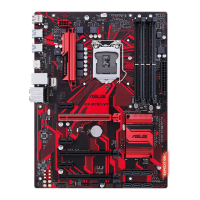
ASUS EX-B250-V7
1-3
Intel
®
B250 Serial ATA 6.0Gb/s connectors (7-pin SATA6G_1~6)
TheseconnectorsconnecttoSerialATA6.0Gb/sharddiskdrivesviaSerialATA
6.0Gb/ssignalcables.
Whenusinghot-plugandNCQ,settheSATA Mode SelectionitemintheBIOS
to[AHCI].
Clear RTC RAM (2-pin CLRTC)
ThisheaderallowsyoutocleartheCMOSRTCRAMdataofthe
systemsetupinformationsuchasdate,time,andsystempasswords.
ToerasetheRTCRAM:
1. TurnOFFthecomputerandunplugthepowercord.
2. Useametalobjectsuchasascrewdrivertoshortthetwopins.
3. PlugthepowercordandturnONthecomputer.
4. Holddownthe<Del>keyduringthebootprocessandenter
BIOSsetuptore-enterdata.
CLRTC
+3V_BAT
GND
Ifthestepsabovedonothelp,removetheonboardbatteryandshortthe
twopinsagaintocleartheCMOSRTCRAMdata.AfterclearingtheCMOS,
reinstallthebattery.
System panel connector (20-5 pin PANEL)
Thisconnectorsupportsseveralchassis-mountedfunctions.
USB 2.0 connector (10-1 pin USB1112)
ConnecttheUSBmodulecabletothisconnector,theninstallthemoduletoaslot
openingatthebackofthesystemchassis.ThisUSBconnectorcomplieswithUSB
2.0specicationsandsupportsupto480Mbpsconnectionspeed.
TPM connector (14-1 pin TPM)
ThisconnectorsupportsaTrustedPlatformModule(TPM)system,whichcan
securelystorekeys,digitalcerticates,passwordsanddata.ATPMsystemalso
helpsenhancenetworksecurity,protectsdigitalidentities,andensuresplatform
integrity.
Serial port connector (10-1 pin COM)
Thisconnectorisforaserial(COM)port.Connecttheserialportmodulecableto
thisconnector,theninstallthemoduletoaslotopeningatthebackofthesystem
chassis
Digital audio connector (4-1 pin SPDIF_OUT)
ThisconnectorisforanadditionalSony/PhilipsDigitalInterface(S/PDIF)port.
ConnecttheS/PDIFOutmodulecabletothisconnector,theninstallthemoduleto
aslotopeningatthebackofthesystemchassis.

 Loading...